 Matthew James Bellafaire
Finally we're here at the end; time to talk about how this thing actually moves. The original bots that my club utilized were remote control tanks, ideally this bot would move and turn just like a tank. I can't manage to find two matching rubber bands to string across the wheels but that was the intention. In order to make this bot move properly the program must be capable of varying the amount of power to each motor, interpreting the relative power to each motor based on input, and be continuous and predictable (it shouldn't immediately turn left if the user is 1 degree off forward).
Varying the speed is simple, since this project uses a L293 all that the program needs to do is send a PWM signal to the EN pins on the channel controlling each motor. In Arduino this is easy, for the ESP32 its more involved but still way less than pure AVR C. using the ledc library we can assign two PWM channels to two separate pins and assign outputs:
  pinMode(O4A, OUTPUT);
  pinMode(O3A, OUTPUT);
  pinMode(O2A, OUTPUT);
  pinMode(O1A, OUTPUT);

  //PWM Setup
  ledcSetup(pwmRightChannel, pwmFreq, pwmRes);
  ledcSetup(pwmLeftChannel, pwmFreq, pwmRes);
  ledcAttachPin(EN34, pwmLeftChannel);
  ledcAttachPin(EN12, pwmRightChannel);
Each pin is labeled in accordance with what it's connected to on the L293. The PWM channel can be written to utilizing the function:
ledcWrite(pwmChannel, val);
Its also worth noting that the resolution is definable with the ESP32, in the case of this sketch its set to a resolution of 8-bits so 0-255.
Now there's fine control of each of the motors, what about direction? That's where the setMotors() function comes in:
void setMotors(int _right, int _left) {
  int rightVal = abs(_right) ;
  int leftVal = abs(_left);
  //
  Serial.print("Right ");
  Serial.print(_right);
  Serial.print(" Left ");
  Serial.println(_left);

  if (_right > 0) {
    ledcWrite(pwmRightChannel, map(rightVal, 0, 100, 0, 245));
    digitalWrite(O2A, HIGH);
    digitalWrite(O1A, LOW);
  } else if (_right < 0) {
    ledcWrite(pwmRightChannel, map(rightVal, 0, 100, 0, 245));
    digitalWrite(O2A, LOW);
    digitalWrite(O1A, HIGH);
  } else {
    ledcWrite(pwmRightChannel, map(rightVal, 0, 100, 0, 245)); //it'll only get here if its zero anyway
    digitalWrite(O2A, LOW);
    digitalWrite(O1A, LOW);
  }

  if (_left > 0) {
    ledcWrite(pwmLeftChannel, map(leftVal, 0, 100, 0, 245));
    digitalWrite(O4A, LOW);
    digitalWrite(O3A, HIGH);
  } else if (_left < 0) {
    ledcWrite(pwmLeftChannel, map(leftVal, 0, 100, 0, 245));
    digitalWrite(O4A, HIGH);
    digitalWrite(O3A, LOW);
  }
  else {
    ledcWrite(pwmLeftChannel, map(leftVal, 0, 100, 0, 245));
    digitalWrite(O3A, LOW);
    digitalWrite(O4A, LOW);
  }
}
for the right motor, we can set the direction of the motor by changing the values on the 2A and 1A pins of the L293, 2A high and 1A low makes the right motor move forward. Changing the pin values to 2A low and 1A high will make the right motor go in reverse. Toggling the EN pin high will enable the right motor and toggling it low will disable the right motor. The PWM signal is fed into the EN pin, since using this method only one pin has to be modified rather than modifying both the inputs on the L293.
Now the bot has XY coordinates coming in and a way to vary the speed and direction of each motor, the program still needs to be able to interpret these values. There's a lot of ways to manage this here's the method I used:
void setMotorsXY(int x, int y) {
  //lets move things to polar, it will make the motor setting much easier since we really only have to look at theta
  double theta = PI / 2; //default to forward
  double rightSpeed = 0;
  double leftSpeed = 0;
  if (x != 0) {  //just some exception handling here
    if (y > 0) {
      theta =  PI - atan2(y, x * (-1));
    } else if (y < 0) {
      theta = 2 * PI + atan2(y, x);
    }
  } else {
    if (y > 0) {
      theta = PI / 2;
    } else {
      theta = 3 * PI / 2;
    }
  }
  double r = sqrt(x * x + y * y) / 100; //we want this value to be less than 1 for later oprations

  if (theta < PI / 2) {
    leftSpeed = 100 * r;
    rightSpeed = (200 * (2 * theta) / PI - 100) * r;
  } else if (theta < PI) {
    leftSpeed = (100 - 400 * ((theta / PI) - .5)) * r;
    rightSpeed = 100 * r;
  } else if (theta < 3 * PI / 2) {
    leftSpeed = -100 * r;
    rightSpeed = (100 - 400 * ((theta / PI) - 1)) * r;
  } else if (theta < 2 * PI) {
    rightSpeed = -100 * r;
    leftSpeed = ( 400 * ((theta / PI) - 1.5) - 100) * r;
  }

  setMotors((int)rightSpeed, (int) leftSpeed);

}
Polar coordinates are the solution!!! Don't read the code just yet, there's a better way to look at it!
First we take the XY coordinates given to the function, then we convert them to polar using the arctangent function, put in a little code to catch some of the weird quirks of the arctan function and we get θ. Then R is calculated by the distance function from the origin to the point. That's all the top half of the code is doing, that's it. The bottom half is where the real magic happens, it converts the direction θ and the distance R into the power % for each motor. The best way to explain how it does this is with a diagram:
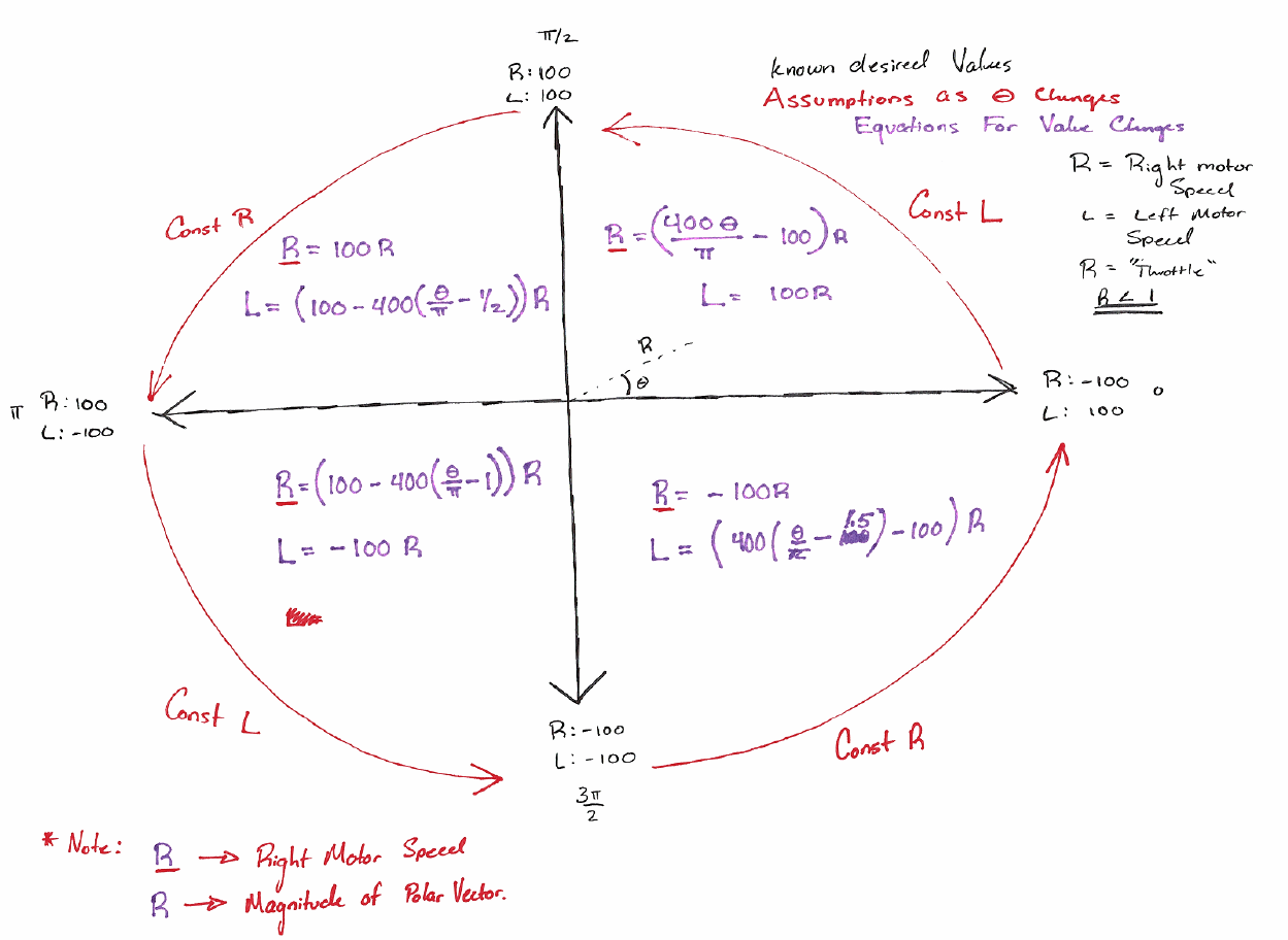
Basically, all this part of the function has to do is figure out which quadrant θ falls into and then use the function that correlates to that quadrant. The primary advantage of this method of control is that each point in the joystick's range of motion correlates to a specific direction/power % of each motor while being overall continuous.
Well that's the whole build story, or found something interesting/useful thanks for reading!
Discussions
Become a Hackaday.io Member
Create an account to leave a comment. Already have an account? Log In.