 Matt Dombroski
The centerpiece of this project and the component that took the most time to develop is the force gauge. The basic idea of most force measurement is knowing the relationship between the displacement of an object to the force that caused that displacement - i.e. a spring. For measuring the force on a control surface of a plane however the 'slip' from a spring is undesired. The servo can only travel so far and in addition any slip will cause a bit of a time delay to moving the control surface.
An obvious answer would be strain gauges. However, strain gauges are extremely sensitive, need quiet electronics (hard to do on an RC plane), and typically need bulky mechanical structures to be attached to. Instead, I happened to read another HaD article featuring [Wold Tronix] linked here, which shows a project with almost an identical goal as this one, and showed a great idea for force measurement. Here an analog hall effect sensor placed over a very small magnet. The hall effect sensor part number is the Allegro A1304 and a 1/32 diameter neodymium magnet are used, as per the recommendation from the article.
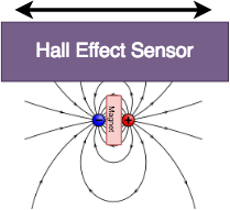
The hall effect sensor is sensitive to both the magnitude and direction of the measured magnetic field. Paired with the small diameter neodymium magnet, the sensor is extremely sensitive small movements, probably in micrometer range up through about 1 or 2 mm. So very little displacement is needed and a stiff, strong sensor body can be designed. This particular hall effect sensor is also very easy to interface, it is completely analog and only needs an analog port on an Arduino or any other embedded platform. One note is that it runs off 3.3V, so watch out before you plug it into the 5V rail of an Arduino!
Now, while [Wolf Tronix] builds in the hall effect senor into the servo arm and into a jig frame for the servo, I wanted to make a more traditional discrete force sensor that was physically separate from the servo. Part of this was because I did not want to modify the servo arms and possibly weaken them, nor did I want to design a frame for the servo that had to be design or at least built into the airframe. I also decided to do this in case I came up with a project down the road which didn't use servo (say stepper motors or linear actuators); I didn't want a design that was bound to a specific servo size and style.
A good force gauge will be linear over its intended measurement range and have low hysteresis so that forces going one direction and then the other read the same values. For my design, I wanted to 3D print the gauge because its faster and more accurate than me hacking at something manually, and I have no access to lathes or CNC's. I went through a number of design ideas:
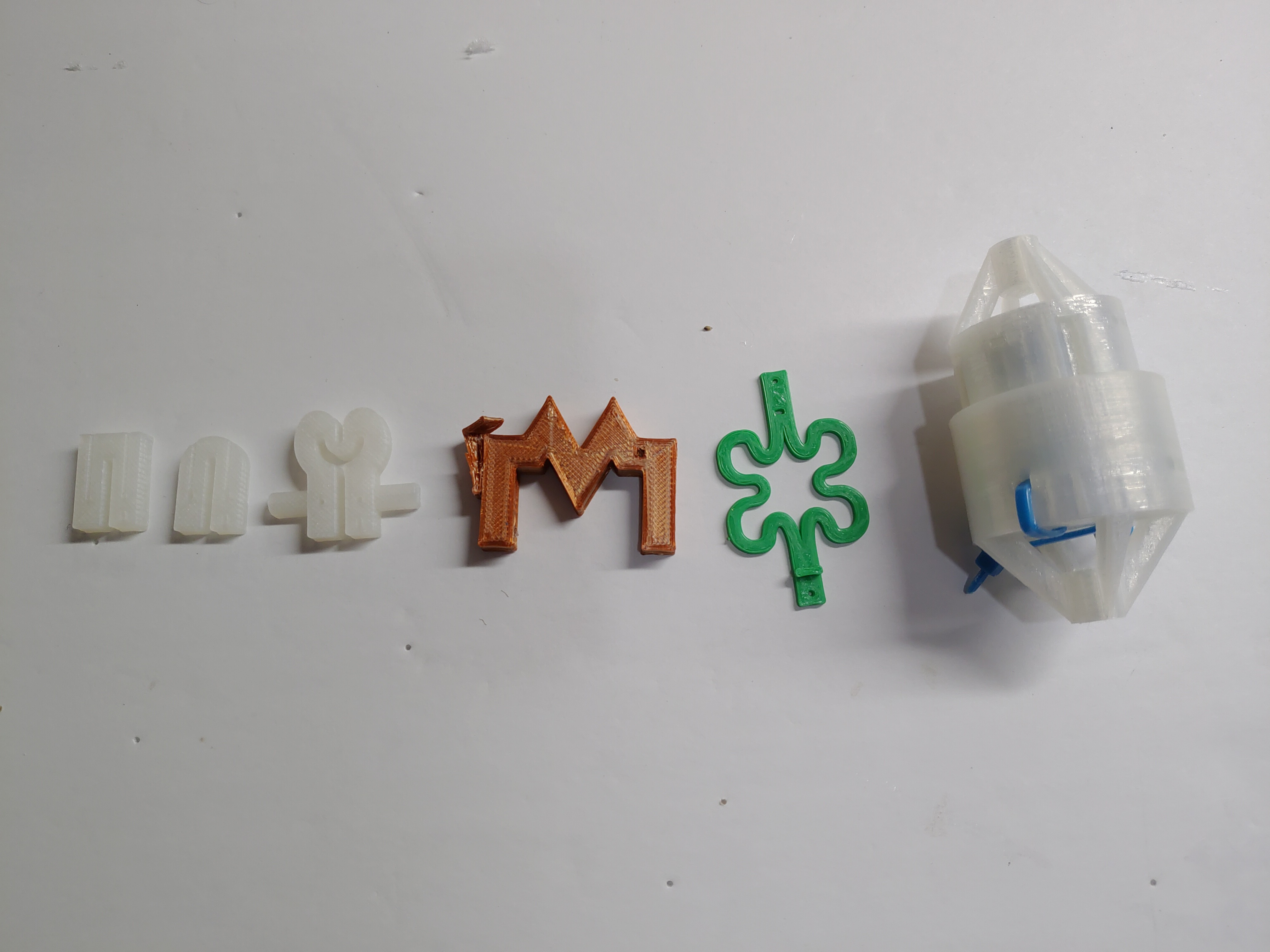
And each had they're own set of drawbacks that took them out of the running. (That big round one at the end would have probably worked well through, just far too heavy for use on an RC plane, and it needed springs more precise assembly...). The design I found to work the best was predictably, one of the simplest:
Why this design? A few things I have observed from testing:
- 'Short' gauges work better overall. Short here means the bending area is small and the arms transferring the force are close together. This reduces the amount of flexing possible, but the hall effect sensor is sensitive enough to need only fractions of a mm of travel. Why keeping the bending area short is useful is due to minimizing undesired flexing directions. For example look at the green clover leaf prototype in the pictures above. As a force gauge it works very well, but because the arms are so spaced there are really two major directions of bending - compression and tension and bending up and down (think bending the plane of the gauge into a curve). Due to the geometry of the sensor, both the compression/tension flexing (of interest) and up/down flexing (of no interest) are measured with roughly equal sensitivity. So the result is looking at my sensor measurements I do not know what type of flexing I am reading, and without additional physical constraints for the second mode of flexing it's not really a useful gauge.
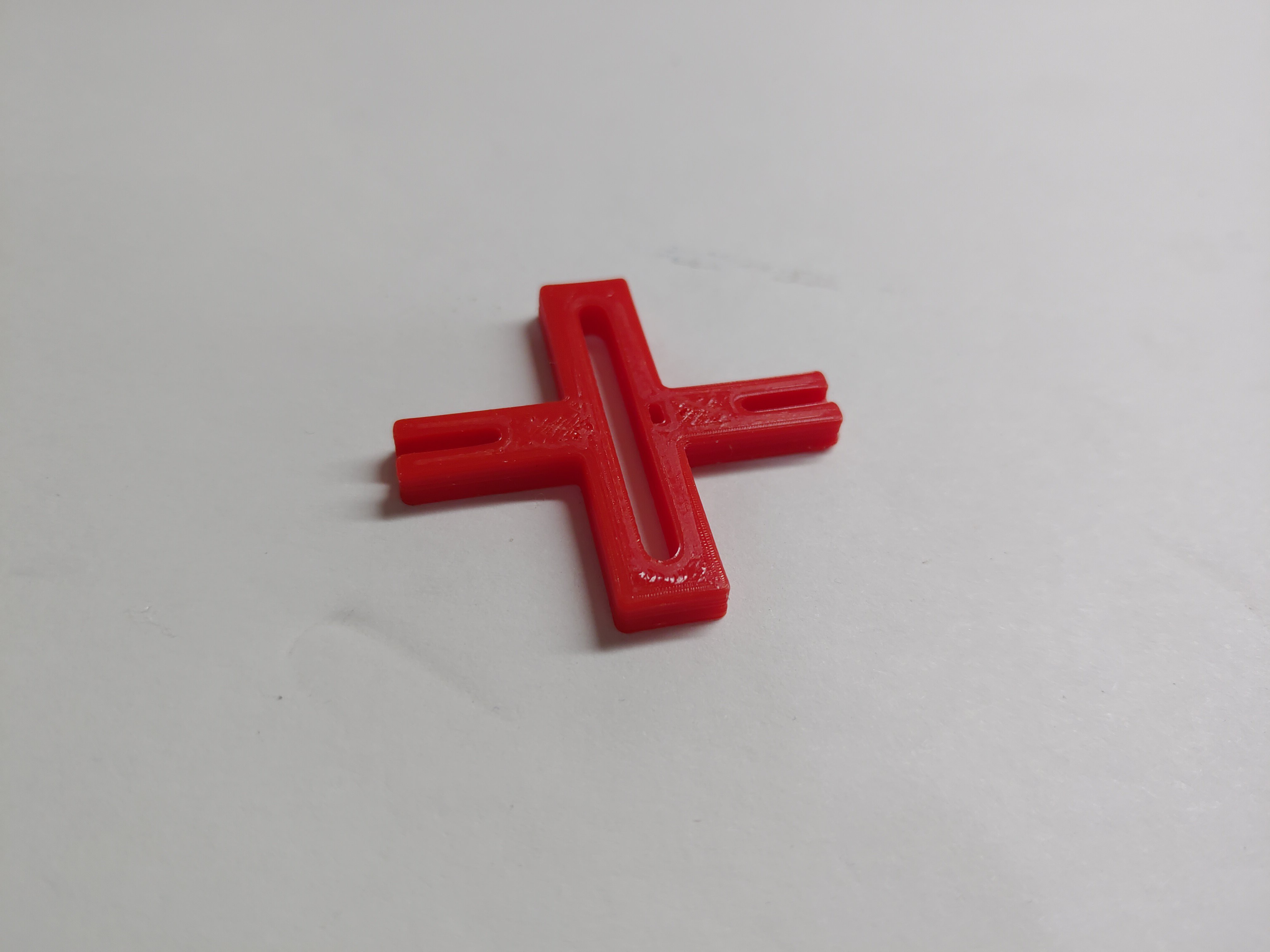
The red square design shown above however, while still technically having the up/down flexing issue, minimizes the distance between the arms and in practice I have not noticed that flexing mode being an issue with this sensor. - The square gauge is better constrained for rejecting other modes of force measurement. Specifically looking at the 'U' shaped sensors above - these sensor were very linear and physically extremely compact but have one huge flaw that makes them useless in practical use. Because the 'U' shape is open ended, any perpendicular force on the attached force rods would directly translate to flexing the sensor and being read as a force. In other words, the rods attached to these sensors would need to be very well physically constrained to always move in-line with the sensor, any flexing unconstrained motion of the rods would be mis-read as an applied force. Because this whole sensor will be floating (not attached to the airframe) such physical constraints would be a pain to plan and set up. The square design being constrained at both ends of the slit/bending area will not have an issue with force perpendicular to its measurement axis.
An stl and step file are attached to the project. I will also try and link to a Fusion 360 design of the part.
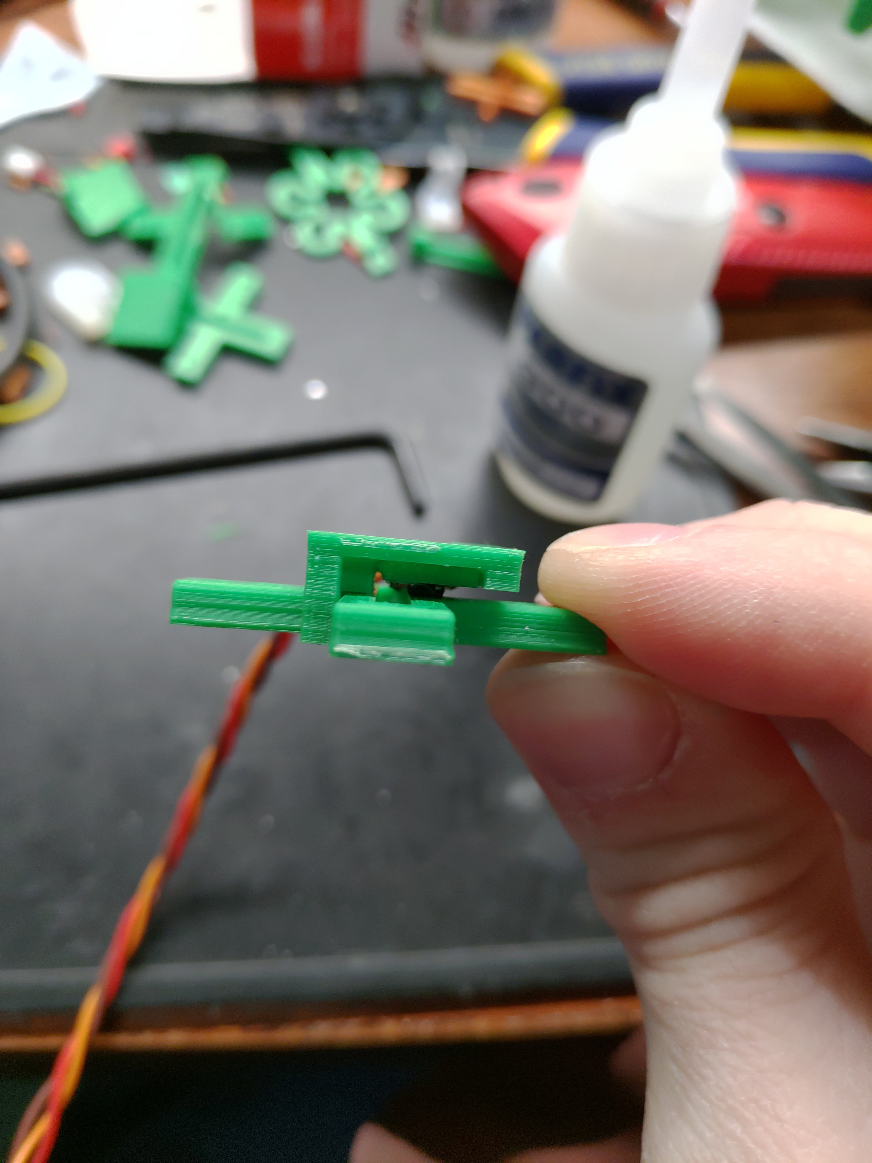
As for how this gauge works, the slit down the middle allows a slight amount of bending as there is a push or pull force applied to the arms of the gauge. The insets in the arms are for holding small rods - there is a hole through the arm, so that the rods can be bent 90 degrees and pushed through the hole in the arms. Some epoxy is then used to set the rods in so they don't move around. The small slot directly to the right side of the slit is where a magnet is inserted and glued in. Then a jig is glued on that holds the hall effect sensor directly above the magnet
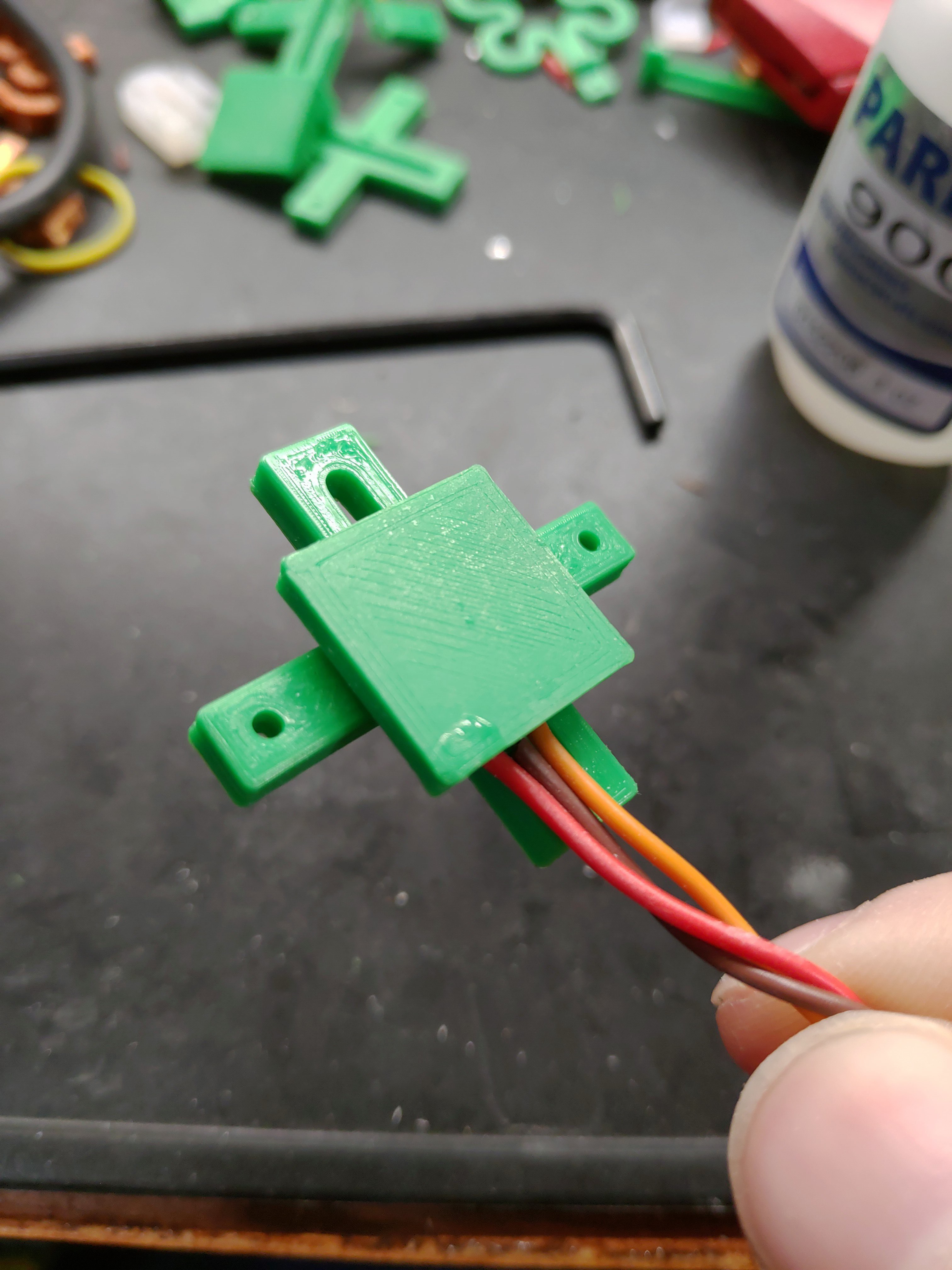
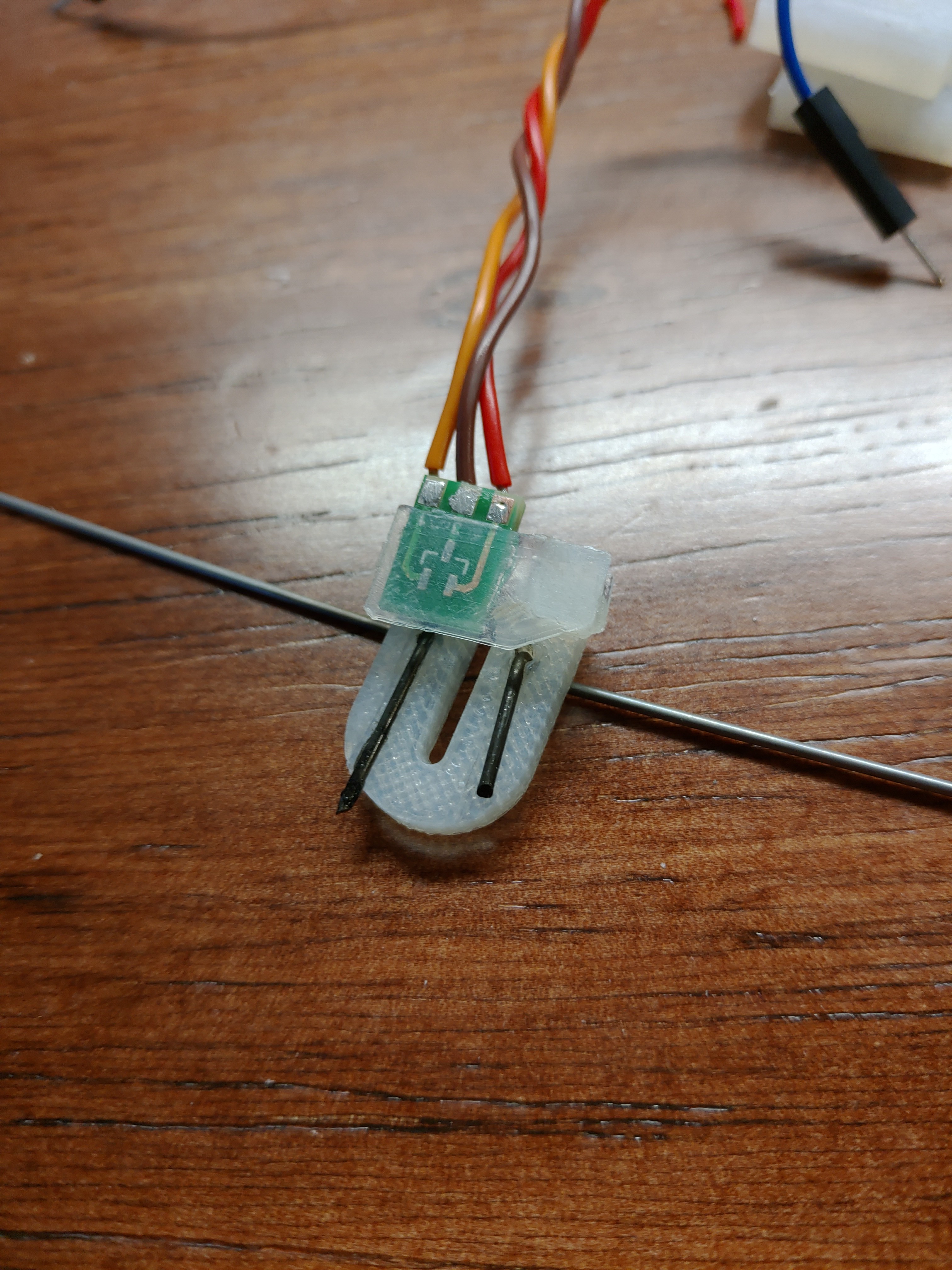
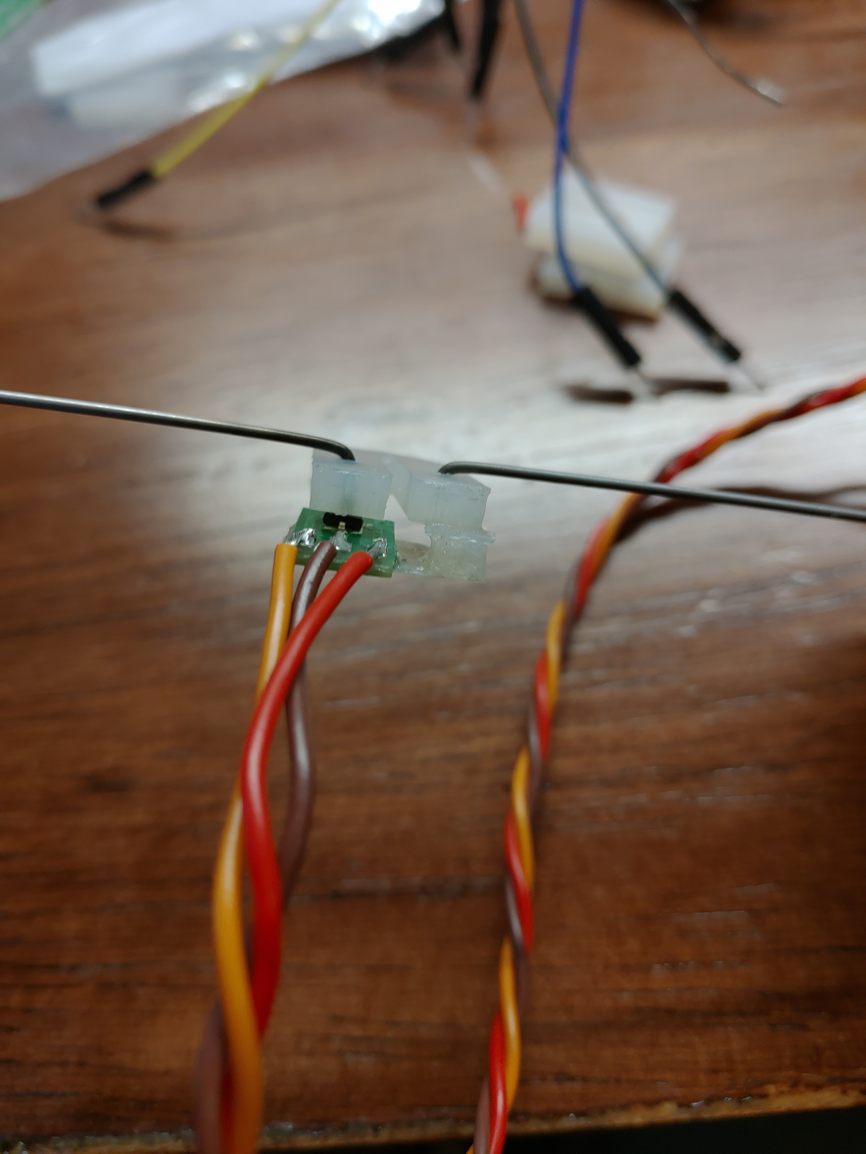
The hall effect sensor is a surface mount, so I have it soldered onto a small circuit board that is also glued to the jig:
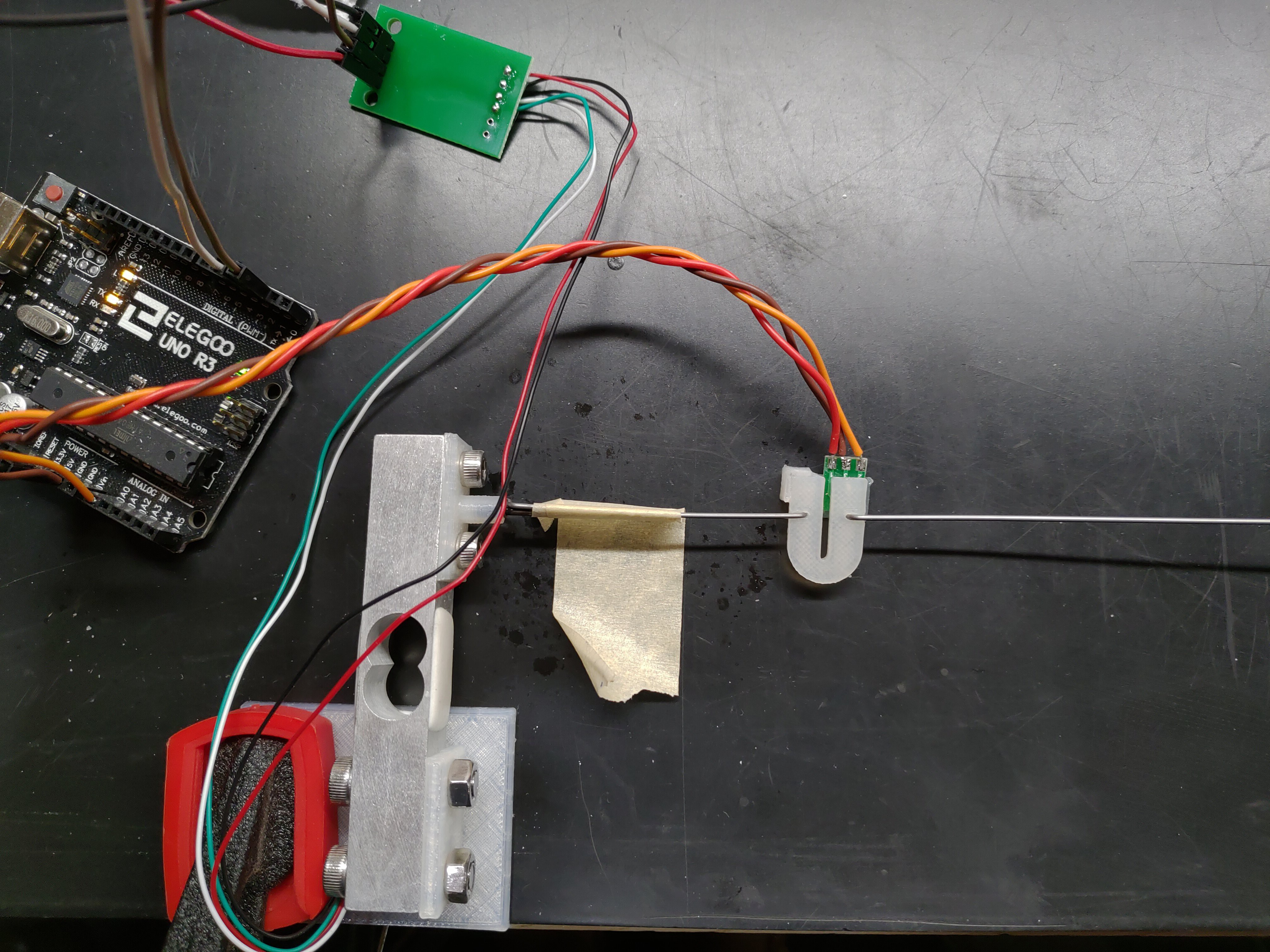
To see how well the sensor preforms, I build a simple test jig using a standard strain gauge as a reference/truth measurement. By comparing the measurements from the 3D printed force gauge to the measurements from the strain gauge, I can get a basic idea of the linearity and hysteresis of the custom force gauge - at least enough to know if its going to cause more issues than help. I do not at the moment plan to calibrate or heavily compensate for non-idealities in the gauges, I just need it to work 'good enough' so that nothing is noticed when controlling from the joystick.
Test setup:
 And a simple plot grabbed from Matlab showing the calibrated load cell vs the printed gauge measurements:
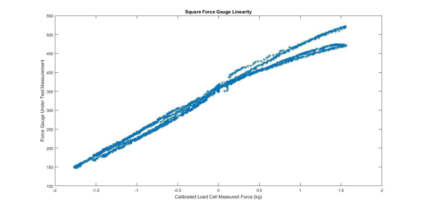 I have not preformed any rigorous calculations for linearity or hysteresis from this graph, it has been really just eyeballing the data and manually testing with the sensor to see how it feels. For now, I am satisfied with this performance and will continue with this force gauge design.
Discussions
Become a Hackaday.io Member
Create an account to leave a comment. Already have an account? Log In.