 Jack Flynn
Black PCB Mock Up and some issues
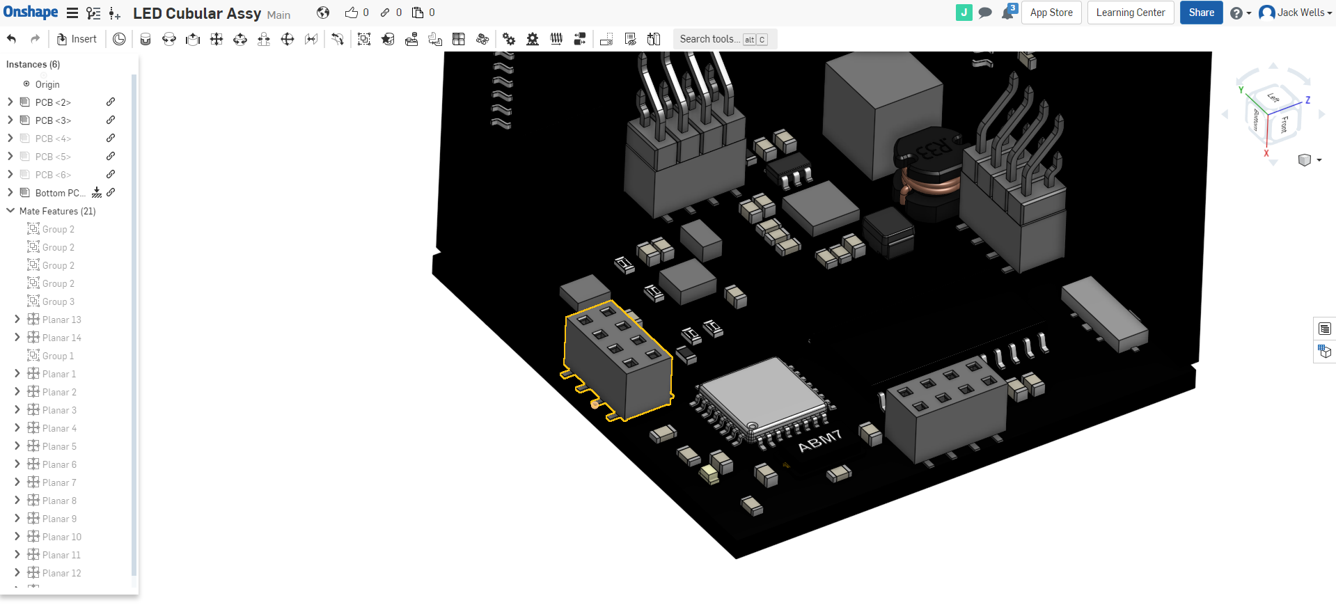
I like to visualise a a project with the big picture. I threw together the PCB steps files into "OnShape" which is a freebie 3d CAD package that also does assemblies. Viewing the cube as a "whole" allows me to check the physicality of the design and it's highlighted a few problems.
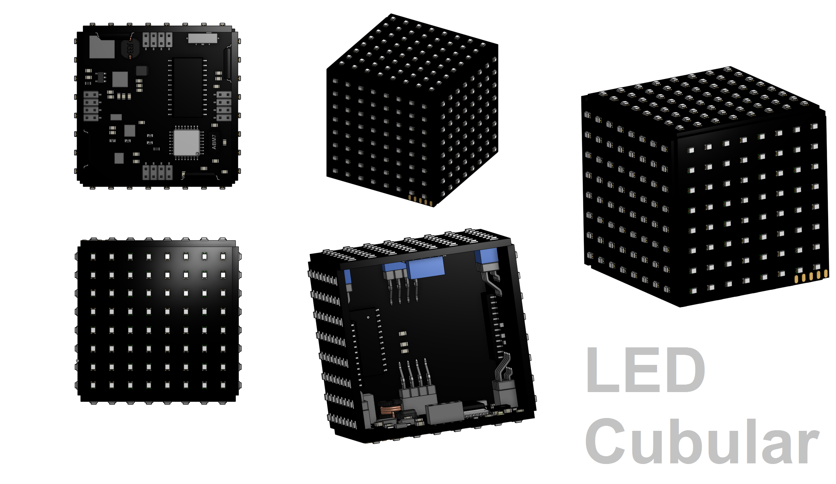
You can check out some 3d views of the LED Cubular in the vid below;
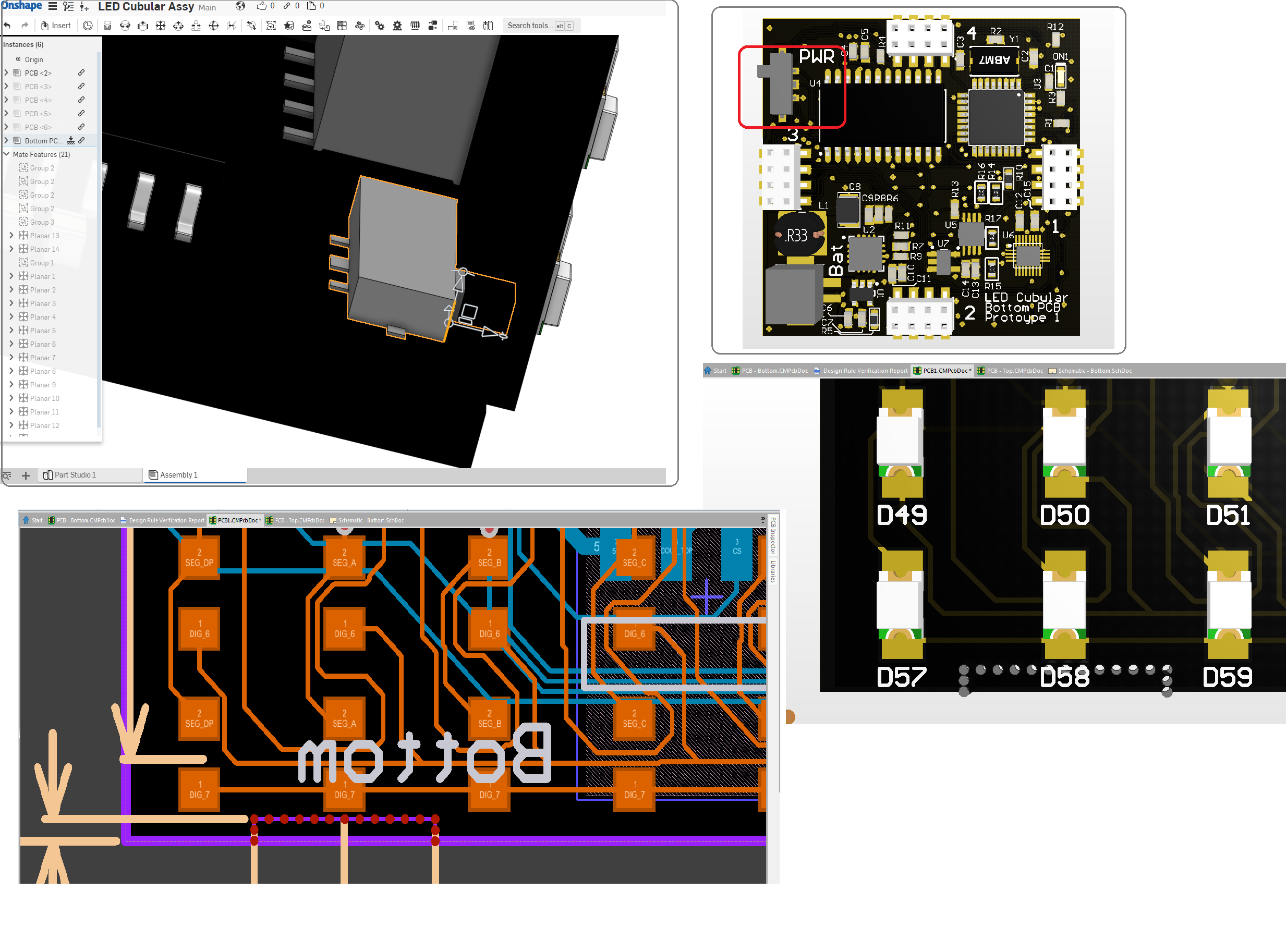
Highlighted Issue 1; Power Switch
In order to shut down the battery powered LED Cubular I wanted to have a small slide switch for on/off. This allows for switching state without having to take the top panel off. However, it means I need a hole in the cube so that I can flick the switch. I don't want to have lots of cut outs on every board so I've decided to add a break-off tab on each of the side panels. That way the one that is placed next to the power switch can be broken off to reveal the switch and the rest can still be relatively solid.
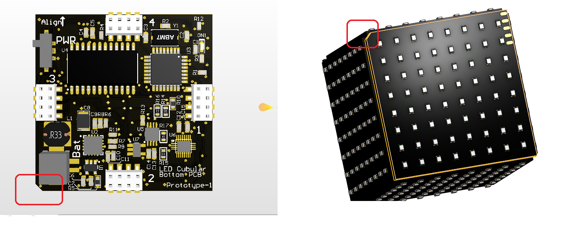
Highlighted Issue 2; Pad Alignment for Charging
One of the further development pieces is to create a "pedestal" for the cube to sit on. This pedestal will provide charging power as well as allow for easy reprogramming of the Arduino within the cube. However, one of my concerns is that it will be difficult to place the cube on the pedestal and get to pads and pins to line up. To help this, I've removed a "keying" corner on the cube. By designing the pedestal with a matching key, it should allow me to ensure that there's a specific orientation of the cube that sits nicely on the pedestal without the risk of misalignment.
Highlighted Issue 3; Connector legs
So final issue I've spotted and was kind of aware of during the design process is that the legs for the connectors on the bottom and top PCBs will be protruding into the area where I want the side panels to be to create a closed cube. Common sense says that in the real world the Side panel PCBs will end up sitting on the legs and that ruins my closed cube ascetic;
You can see in the image that the legs of the connector are right up the board edge which is where the side panels should be flush. In order to overcome this I'll need to plot out small cuts in the side panel design that gives clearance to each of the pin legs on the bottom and top PCB. Totally doable, just takes a bit of thinking ahead.
Discussions
Become a Hackaday.io Member
Create an account to leave a comment. Already have an account? Log In.