 Alastair Hewitt
It was a year ago when I stumbled across the infamous 8-bit Guy video demoing the Gigatron. I was working on a retro arcade cabinet at the time, but building a video game system from scratch was a much more interesting challenge. It wouldn't be the first time either. I built a Racer game out of TTL chips using a 7x7 LED matrix as a senior project at school. I then spent that summer working on a Harvard Architecture CPU with a ROM-based ALU. I never thought about generating VGA (it was still a couple of years away at the time) but seeing the Gigatron achieve this with so little has re-inspired me!
I'm essentially at the same place I was almost 12 weeks ago: I can copy an image from the ROM to the video RAM and generate the video timing. What has changed is the way the video timing is generated and how this code is built.
The initial code was developed old skool by assembling the machine code by hand and then typing the hex code into the WIndows app that came with the EPROM programmer. It was nostalgic, but not very productive (not to mention frustrating when you typo '6' instead of 'b').
The project now has an assembler and a build script to compile the code, calculate the ALU lookup tables, and generate fonts. The final step of the build process is to flash the ROM image using minipro. There is no simulator though, so testing must be done on real hardware and debugging still requires an oscilloscope.
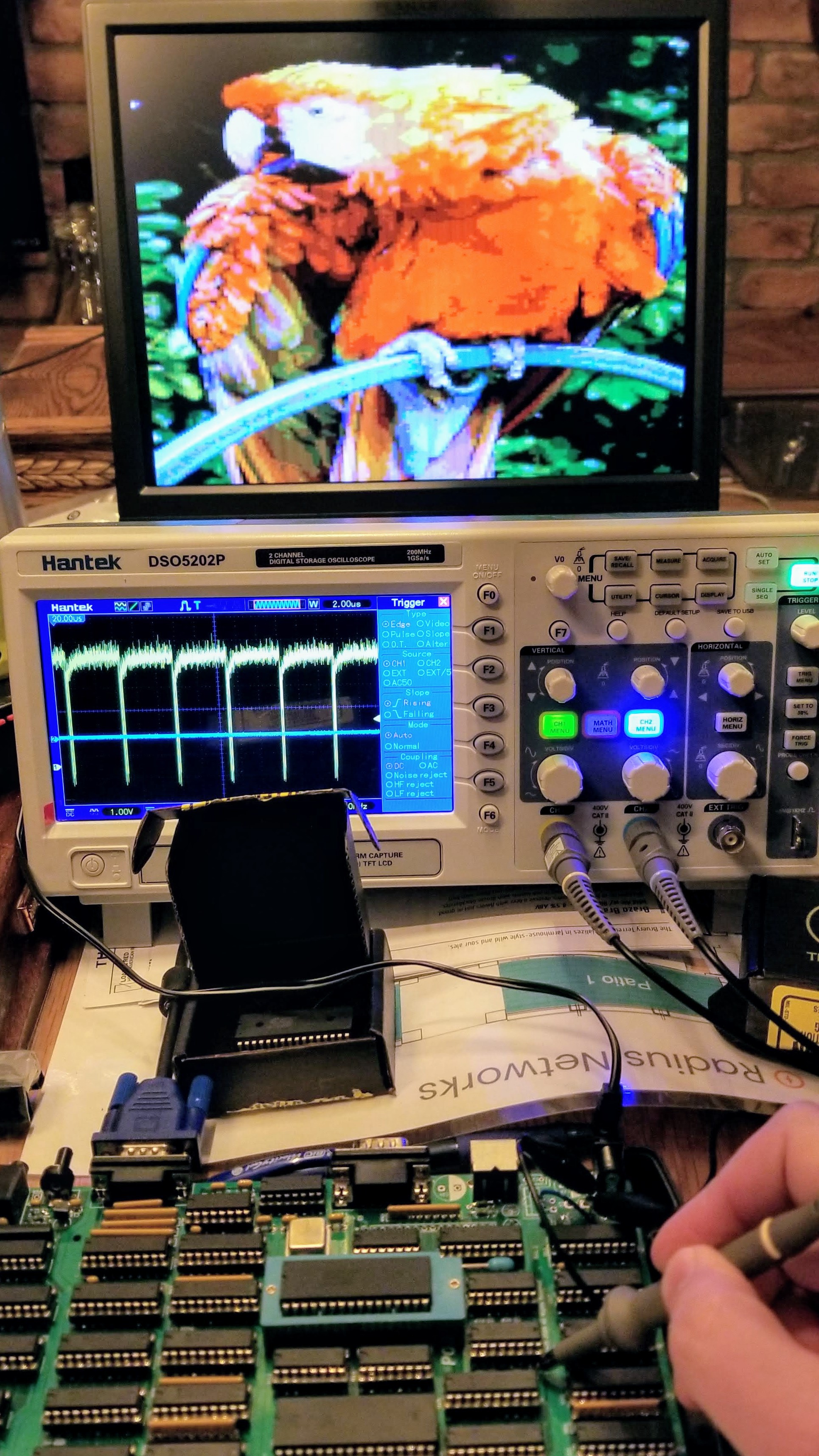
The oscilloscope trace above shows the Page Register clock pulse occurring every 52uS. This represents the virtual machine clock of a hardware abstraction layer developed over the last few weeks. This is the foundation of the system going forward and will be providing video, a virtual UART, "sound chip", and CPU for an operating system and user applications.
Hardware Abstraction Layer
There are multiple systems on the board with timing critical requirements like the video, audio, and serial ports. A user program can not take control of the hardware without having a significant insight in to the various timing constraints and requirements of these systems. The solution is to put an abstraction layer between the hardware and user program.
Even though this has drifted up and down a bit, the final dot clock (until it changes again!) is 33 MHz. This drives a 4-phase clock for the hardware process clock of 8.25MHz. The hardware abstraction layer divides this clock down to a 43-cycle fixed virtual machine cycle running at 191.86kHz. This is further divided down to 9.593kHz by using 20 machine cycles to create a virtual process cycle consisting of either 4 lines of 5 cycles, or 5 lines of 4 cycles.
Each line in the process cycle ends with a single machine cycle dedicated to timing. This cycle updates the scan register to generate the video sync pulses, updates the V register to select the next line for the GPU to render, samples the serial ports, and decides what additional cycles are needed to handle features (audio and serial communication).
The remaining cycles are available to execute user code on a virtual CPU. So the 4-line process cycle has 16 machine cycles (153,488 per second) and the 5-line process cycle has 15 machine cycles (143,895 per second) to execute user code. The virtual CPU uses a fetch/execute cycle, where the execute would need at least one and sometimes two machine cycles. The average would be around 2.3 cycles per instruction, which equates to a virtual CPU speed of around 66k instructions per second.
Video
The ALU now contains a video timing function to support four video timing schemes. The first two use the 4-line virtual process cycle with a horizontal frequency of 38.372kHz. The first of these uses 128 process cycles per field to generate VGA at 75Hz (VESA DMT ID: 06h). The second uses 160 process cycles per field to generate SVGA at 60Hz (VESA DMT ID: 09h). The last two timing schemes use the 5-line virtual process cycle with a horizontal frequency of 47,965kHz. These both use 160 process cycles per field, with the first generating XGA at 60Hz (VESA DMT ID 10h) and the second supporting the latest VESA CVT reduced blanking v2 (CVT 1.01MA-R).
There are 8 ways to divide down the vertical timing in the 4-line cycle modes (VGA/SVGA): divide by 2, 3, 4, 5, 6, 8, 10, 16. The divide by 2 and 3 are normally used for hi-res graphics (bitmapped, 8 colors). The divide by 4, 5, and 6 are used for lo-res graphics (bitmapped 256 colors), and 8, 10, and 16 are used for the text modes. The 5-line cycle (XGA) can only fit 6 ways: 3, 4, 6, 8, 10, 16.
There are also three hardware bits to control the GPU: mode1 - 1 or 2 cycle timing (used to select text vs graphics mode), mode2 - video DAC (8 or 256 colors), mode3 - reduced blanking on/off (only used for CVT).
A single byte is used to define the video mode, but only 7 bits are needed. There are a total of 112 addressable video modes. Some are not too useful, but many of these are. In general there will be hi-res/lo-res bitmapped graphics and normal or compressed text modes in either 4:3 or 16:9 aspect ratios.
One final note on the horizontal resolutions. The 33MHz dot clock is close to the native clock of the 75Hz VGA timing to render the standard 640 resolution. The other timings expect a faster dot clock that will render as a lower horizontal resolution. The 33MHz dot clock is about 80% of SVGA and will also render with a resolution of 640 (80% * 800), but only to 512 in XGA (50% * 1024). Both the VGA and SVGA modes support 80 column text, but XGA is closer to 64. However, the final mode uses CVT timing with reduced blanking (only supports newer LCD monitors). The ALU timing function generates timing for a 1295 x 777 at 60Hz mode assuming a 66MHz dot clock. This is exactly twice the actual dot clock so the rendered resolution is now close to 640 and can also support 80 columns of text.
Serial
There are two serial ports and each one has two bits in and out. One port is used to communicate via the RS232 interface and the other supports the keyboard. This is where the specific frequency of the virtual process cycle also comes in to play. The process cycle is aligned to support communications at a 9600 baud rate with the transmission of one bit per process cycle.
The sync code for the video timing only uses about half the 43 hardware process cycles leaving the other half to process the incoming serial stream. Another custom ALU function is used to sample the serial inputs and drive a state machine. The final state determines if and what data was received over the ports at the end of the virtual process cycle.
The data input of the RS232 interface is more or less aligned with the virtual process cycle, but will drift slightly. Sampling over more than one line can identify the drift and compensate to determine the value of the input bit correctly.
The keyboard is a little more complex. The PS/2 interface generates its own clock and this frequency is defined over a range of 60-100uS. The virtual process cycle is 104uS, so one or two bits could be sent in a single cycle. The state machine outputs two values to determine if zero, one, or two bits were received and their value.
Both serial ports have hardware flow control and even though the serial interface is sampled all the time, the serial communication is a feature that is turned on/off. When turned on the output of the serial sample state machine is processed by an additional machine cycle during the process cycle.
Audio
There are no resources dedicated to the audio unless the audio is turned on as a feature. When turned on an additional machine cycle is used to handle the audio state and then one machine cycle is required per voice, up to a total of four voices. Each voice is sampled once per process cycle, at a rate of 9.6kHz. This limits the highest frequency to 4.8kHz, but is high enough to support the full 88-key piano scale.
CPU
Work is currently underway to implement a binary compatible version of the RCA 1802 COSMAC microprocessor. This is a huge subject in its own right, so I won't go in to the details here. One thing to note with this design though. The virtual machine cycle will map almost 1:1 with the COSMAC machine cycle. The COSMAC required 8 clock cycles per machine cycle, so the hardware abstraction layer is running at the equivalent of 1.23MHz, or about 70% as fast as the COSMAC Elf/Pixie.
Discussions
Become a Hackaday.io Member
Create an account to leave a comment. Already have an account? Log In.
That's sooo awesome!
Are you sure? yes | no
From all the software efforts we made, the ones that added software compatibility with something else (at whatever level of abstraction) invariably yielded the most progress. Looking back, I believe that in terms of effort the Gigatron project has become a 80% software project, 10% hardware, and 10% "kittification".
Are you sure? yes | no
The rest of this year is going to be 80% software, well actually what I call firmware - building out the virtual machine. I don't think I'll be building any "apps" until next year. Getting this abstraction layer in place was a huge breakthrough though. The code is now modular so I don't have to recalculate all the timing when I change something. That would always break things and I would spend hours debugging with the oscilloscope. I just tested the fetch code and it worked first time! The machine is now incrementing a 16-bit virtual program counter and scanning the entire lower bank of memory... it doesn't do anything with what is fetched yet, but it is now easy to add each instruction and update the decode lookup table to execute the code. It just has to fit in 43 cycles.
Are you sure? yes | no