Prelude:
A Chinese knockoff battery charger fell into the shopping basket while ordering some electronic toys from a Chinese vendor.
Don't turn it on, take it apart.
Inside there is an MCU with all markings removed. The Internet is also guessing about brand and type of the MCU used in those chargers.
Ok, now you got me interested.
Guesswork, consulting datasheets, googling through Internet forums and comparing pinouts leads to a device MC96F6432 from ABOV (a Korean company, http://www.abov.co.kr) as a likely candidate. There are datasheets and documentation available for these MCUs, however the information about the ISP/debug interface (OCD) is very limited (not to say incomplete and inaccurate). With some (documented) logic-level wiggling on the OCD pins we managed to get the MCU into debug mode after power up, but not much further due to the sparse information in the datasheet. As this confirms our guess about the used MCU brand and family, it’s time to take it to the next level: learn about the OCD protocol and how to use it.
The ABOV MC96F family consists of an 8051 core with additional FLASH, external RAM and quite some extra on-chip hardware and would make an interesting candidate for some small hardware projects. Thus, the lack of open source tools to program and debug this device is somewhat “irritating”, so we are about to change that...
Act 1: first steps
Let’s go shopping:
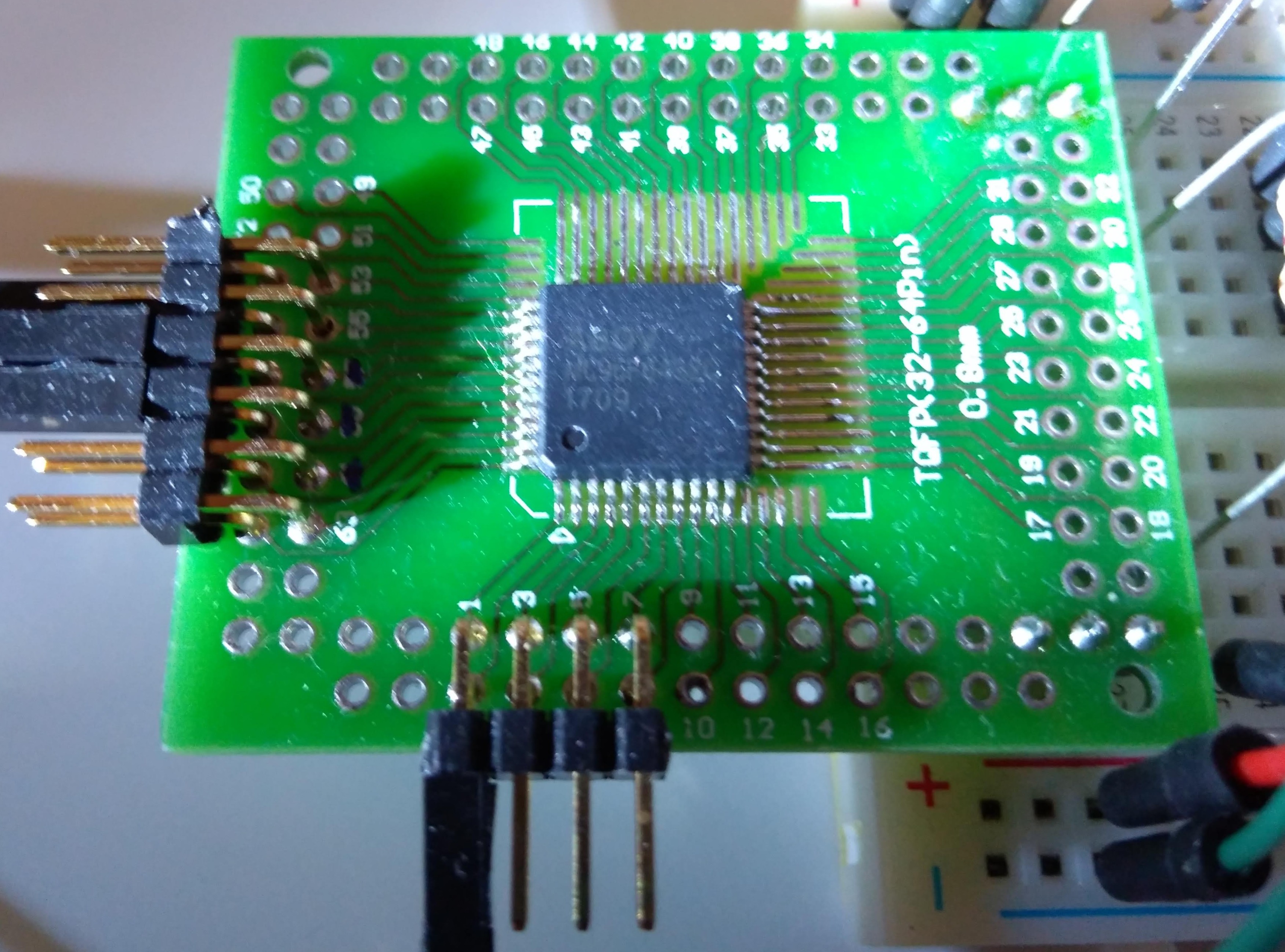
- Some ABOV MC96F6432 MCUs to play around with - check
- PLCC adapter boards - check
Other equipment, such as a Buspirate, logic analyzer and spare Arduinos boards are part of every reasonably equipped lab - or should be.
As mentioned, the documentation in the ABOV data sheets covering the OCD interface is superficial and is missing quite some relevant information. Rather quickly we had to accept that approaching our project from this side would not succeed. And this is the part where the real fun is about to start.
Reverse engineering - the art of getting to understand a black box (or partial black box).
Challenge accepted.
Act 2: to reverse engineer something you need something to reverse engineer
OK, we need an OCD adapter and get the official software working, then start to reverse engineer the OCD communication. Searching for an ABOV OCD adapter shows that they are hard to find in Europe.
But it turns out that ZILOG has a very similar MCU family... Even the datasheets are basically 1:1 copies of the ABOV documents (some diagrams even have not been rebranded properly and still show the ABOV brand). Even the downloadable Windows software for the OCD adapter looks the same. Soo... let's assume that those MCUs are compatible/identical. It actually looks like the ZILOG chips are just rebranded ABOV MCUs.
We organized two sets of Zilog OCD adapters, one original ZILOG OCD adapter and one ET-Z8051 OCD adapter, ordered from an Asian supplier. Both OCD adapters are working with the ZILOG software, but both adapters refuse to work with the ABOV software.
Act 3: reverse engineering the tools we want to use to reverse engineer
So we tak a detour in first reverse engineering the OCD adapters - void the warranty!
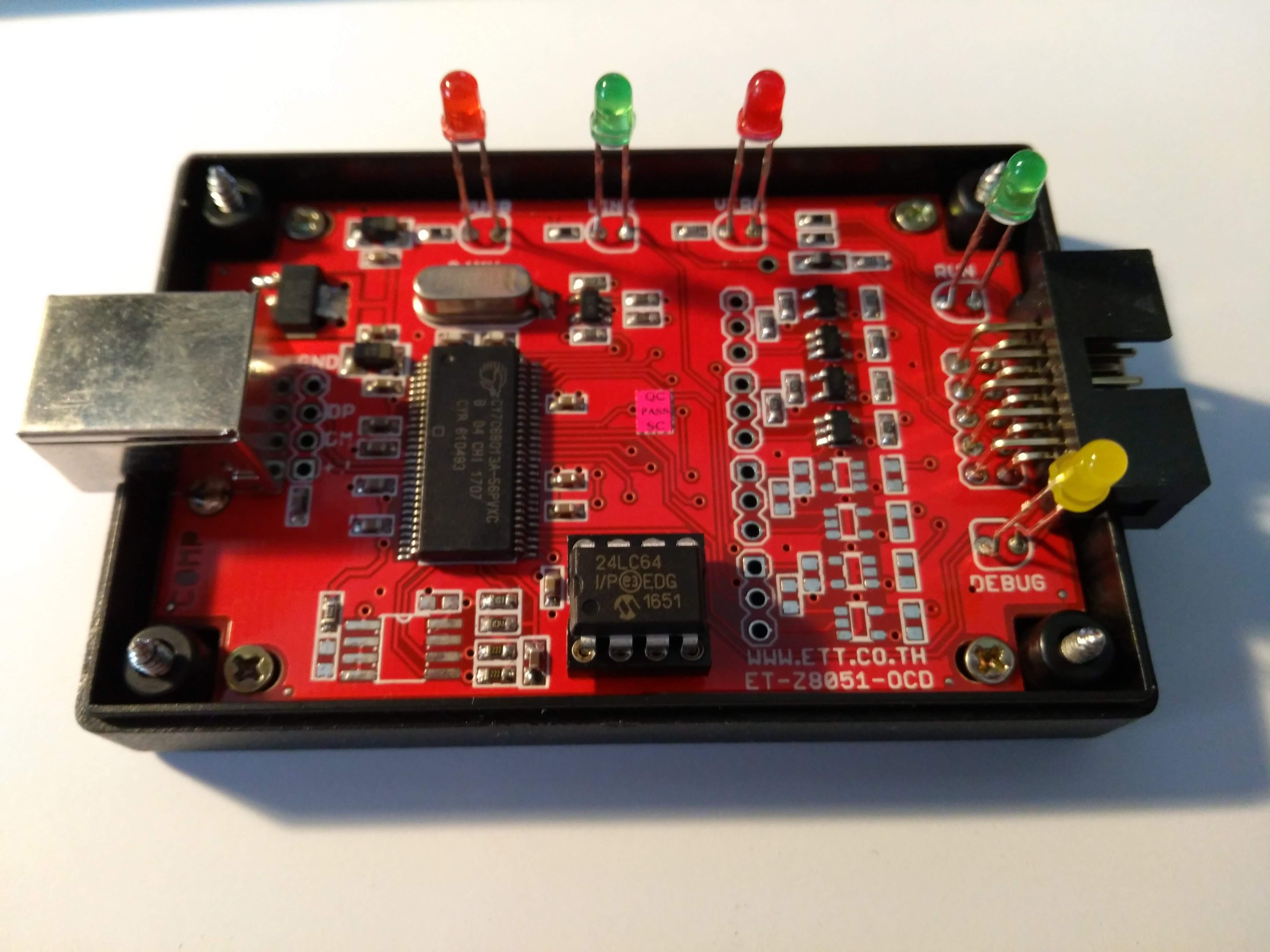
ET-Z8051 OCD adapter:
Zilog OCD adapter:
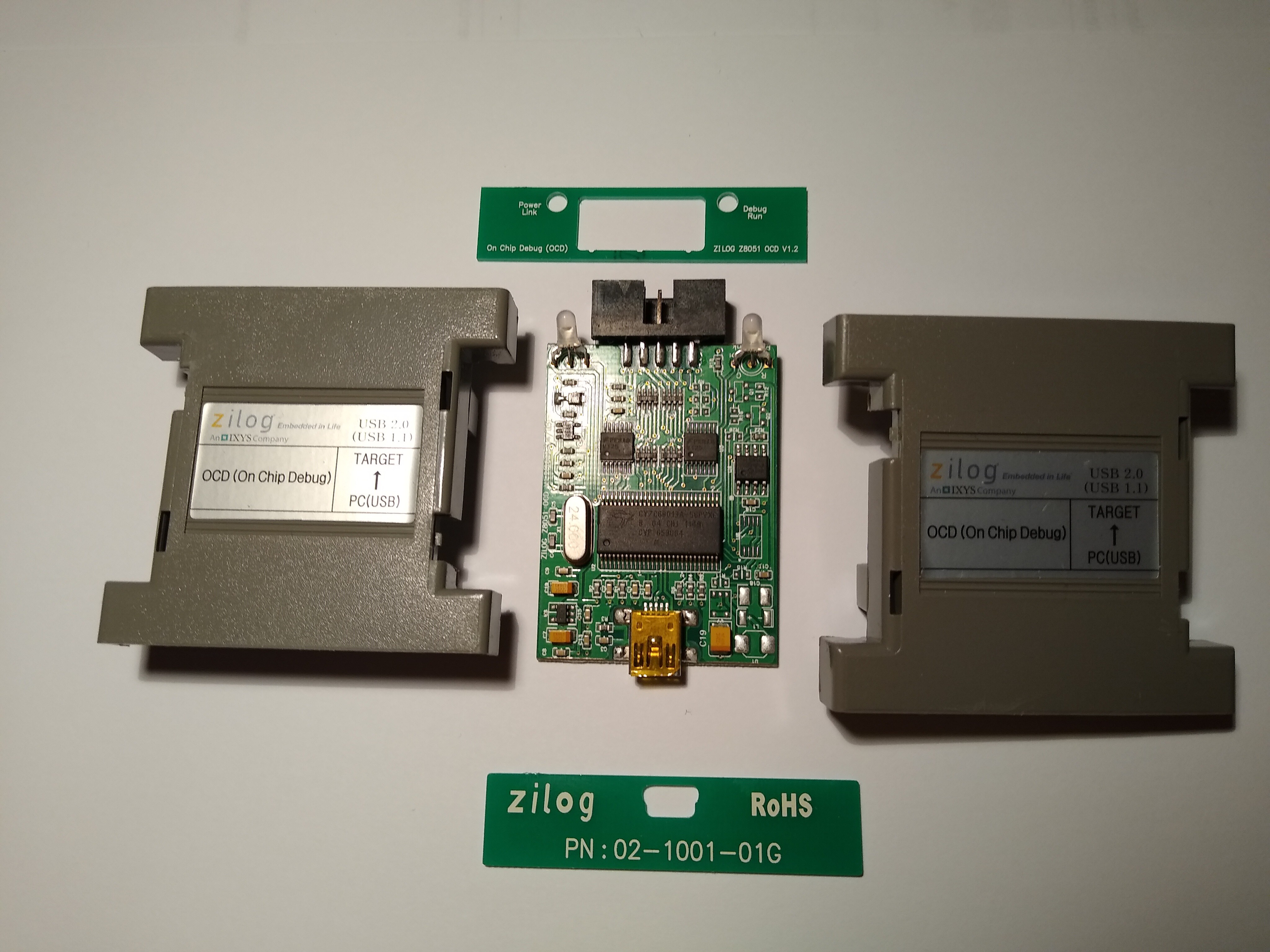
There is a Cypress EZ-USB chip inside. So let’s look for Cypress documentation and learning about those chips and their firmware/boot behavior. A first educated guess is that the only differences between a ABOV and a ZILOG OCD adapter are the USB vendor and product IDs. Cypress provides really good documentation about their hardware. After reading some of the available Cypress documentation about the boot procedure it is evident that the USB vendor and product IDs are stored in the attached i2C EEPROM and the firmware image is downloaded by the driver. The VID/PID used by ABOV and ZILOG are different and exposed in the Windows drivers .inf files.
So, we could just pop out this EEPROM and read/reprogram it - but that would...
Read more »


 Dave's Dev Lab
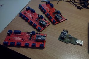
 Necromant
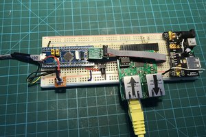
Binary files for Win32(cross compile support MinGW):
fxload.exe -
For the fxload utility to see the device, you need to install libusb-win32 filter for the device.
z8051_dude.exe -
To z8051_dude added feature to select baud rate for any other Arduino (19200,57600,115200(default))
Accordingly, it is necessary to compile the firmware for the Arduino with the chosen baud speed parameter in Makefile (-DBAUD_RATE=<baud>)
https://www.mediafire.com/file/xw4a8xzdamea36o/win32_z51dude.zip/file
Thanks for your project.