 Ted Yapo
This was a quick project to see how far I could push a 555-style RC relaxation oscillator. The current fastest commercial offering is TI's LMC555, which the datasheet says has a maximum frequency of 3 MHz. Microchip offers the MIC1555/57 parts, which are missing a few pins relative to the traditional 555, but run to 5 MHz.
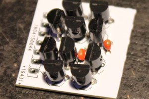
Looking over the possibilities for fast comparators, I found the ADCMP600, which offers a 3.5 ns propagation delay and runs from 2.5 to 5.5V. I decided to couple this with a latch built from a 74LVC2G02 dual-NOR, with a typical Tpd of 1.8 ns at 5V. Adding three resistors and a few bypass caps turns these IC's into a 555-like part that runs way faster than the available integrated ones.
It's not practical by any means - and RC relaxation oscillator in the VHF frequency range is a silly idea, and the comparators cost almost $5 each. There might be a use for a fast one-shot using this circuit, but it was mainly built just for the fun of seeing how fast it would go.
The Design
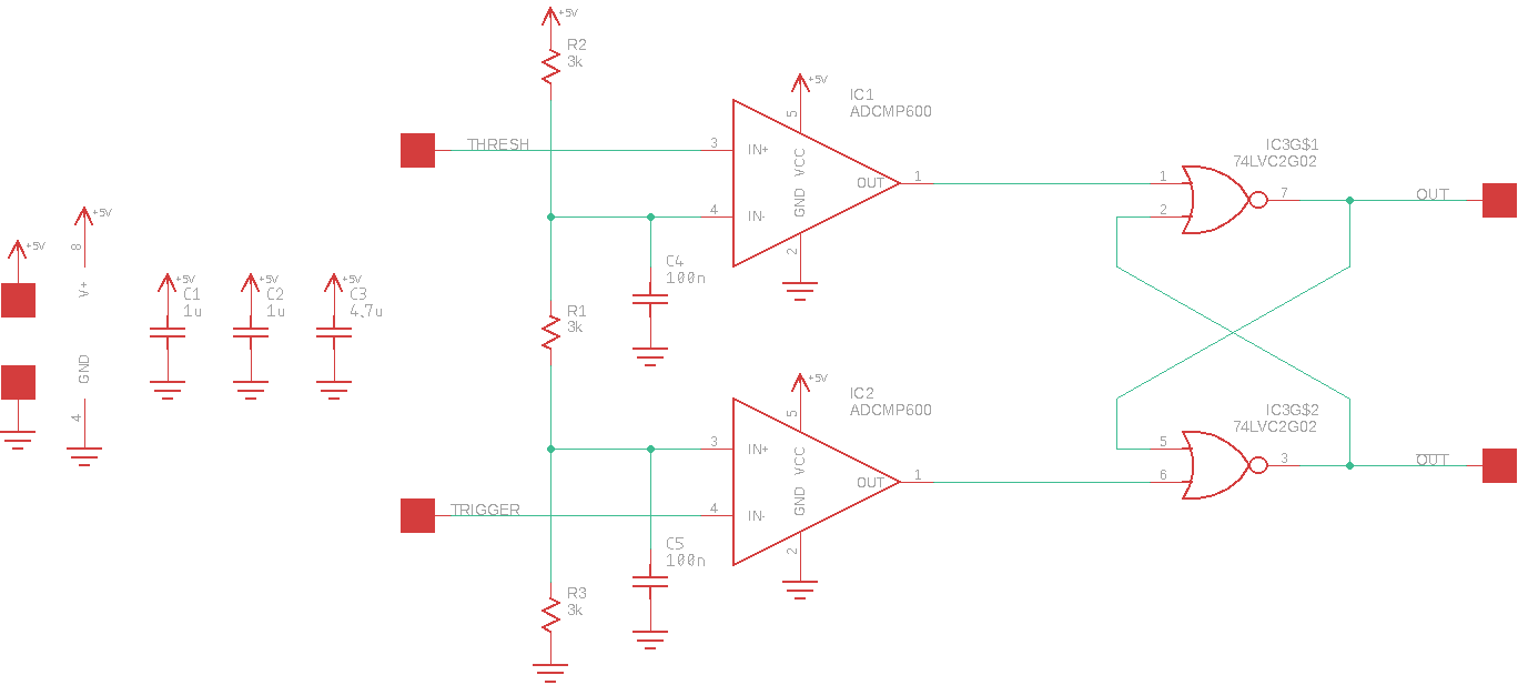
This circuit, not surprisingly, looks a lot like the insides of a 555. There is a voltage divider made from three 3k resistors that creates two reference voltages based on the supply. I added two bypass capacitors on those references, although you could leave one or both out if you wanted to vary either reference like you can with the CONTrol voltage pin on a real 555. One comparator senses when the THRESHold input exceeds the upper reference, while the other senses when the TRIGger input goes below the lower reference. The comparator outputs drive an RS latch made from the two NOR gates. This provides a true and inverted output.
The Eagle design files as well as gerbers are available in the GitHub repo, and the PCB is shared on OSH Park.
So, How Fast Is It?
So far, I've only tested the board in astable (oscillator) mode. In this mode, the THRESHold and TRIGger inputs are tied together, and driven from a capacitor to ground. The capacitor is alternately charged/discharged by a resistor from the non-inverting output. I measured the output from the inverting port with a resistive 10:1 probe made from a 453-ohm resistor and a length of RG174 cable fed into a 50-ohm terminated oscilloscope input.
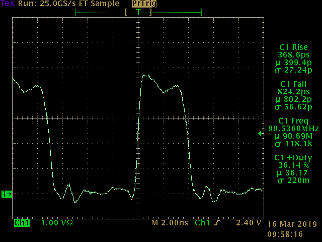
With no external R or C at all, the circuit oscillates at around 90.5 MHz. This frequency depends on temperature, the supply voltage, and to a large extent, the characteristics of the individual comparators and NOR gates. The duty cycle is also pretty low (36%). An interesting note is that the rise and fall times are both well under 1 ns: the rise time is around 400 ps, while the fall time is around 800 ps. This is around 150x as fast as the bipolar 555s with their 100 ns transitions, and 25x as fast as the TLC555 and MIC1555/57 at 15 ns.
You'd never use it like this, though, because the frequency is really unstable.
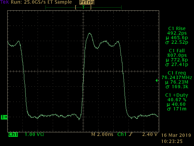
Adding a 10 pF capacitor and 39 ohm resistor brings the frequency down to 76 MHz, although the influence of the circuit itself is still probably too high at this point.
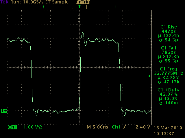
A more reasonable 100 pF / 100-Ohm combination results in 32.7 MHz oscillation, and a duty cycle closer to 50%.
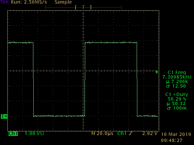
Finally, dropping well into the original 555 range with a 100 nF capacitor and 1k resistor makes the output a perfect-looking 7.3 kHz.
Conclusions
Yeah, you can make a 555-like timer from fast comparators and NOR gates. Is it useful? I don't know. It was fun to play with, though.


 Yann Guidon / YGDES
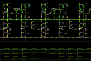
 Tim
Tim
https://cdn.hackaday.io/images//856311555584600515.jpg