 Matt Bradshaw
DrumKid is now available to buy from https://mattbradshawdesign.com/store/
Drum machines are ubiquitous in modern music, but playing them live presents a challenge. When playing electronic rhythms live, whether using a drum machine or a laptop, it can often appear that a musician is simply pressing "play" on a backing track, removing much of the perceived spontaneity of a live performance.
My drum machine, DrumKid, aims to tackle this problem by using a variety of controls to alter a drumbeat live, using randomly generated drum hits which augment the original beat. Rather than being designed as a pre-programmed backing instrument, DrumKid aims to be a playable instrument in its own right, with continuously adjustable controls that work well in a live setting. My intention was to create an engaging, interactive device that, like any musical instrument, can be mastered over time with practice.
DrumKid has the following features:
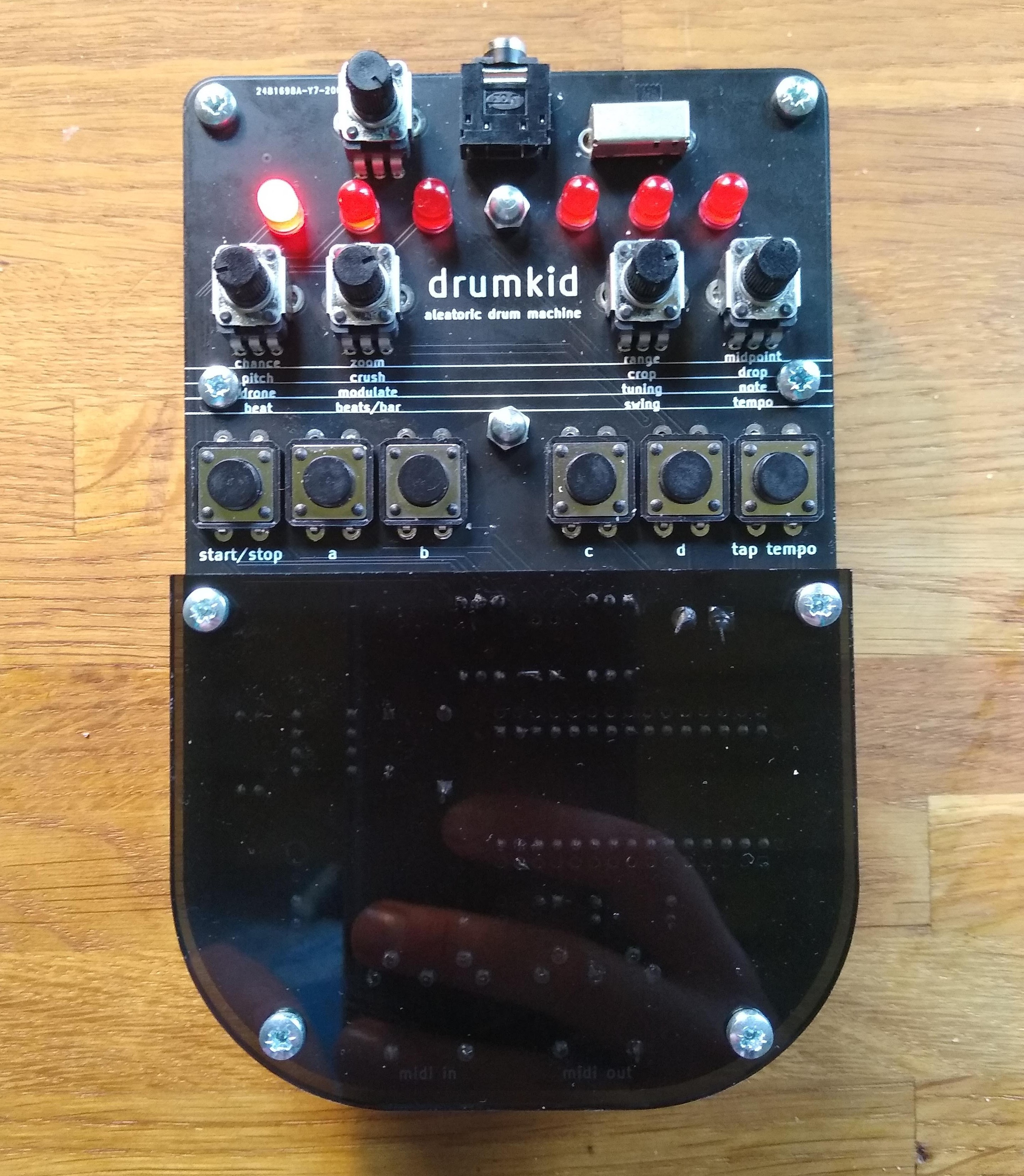
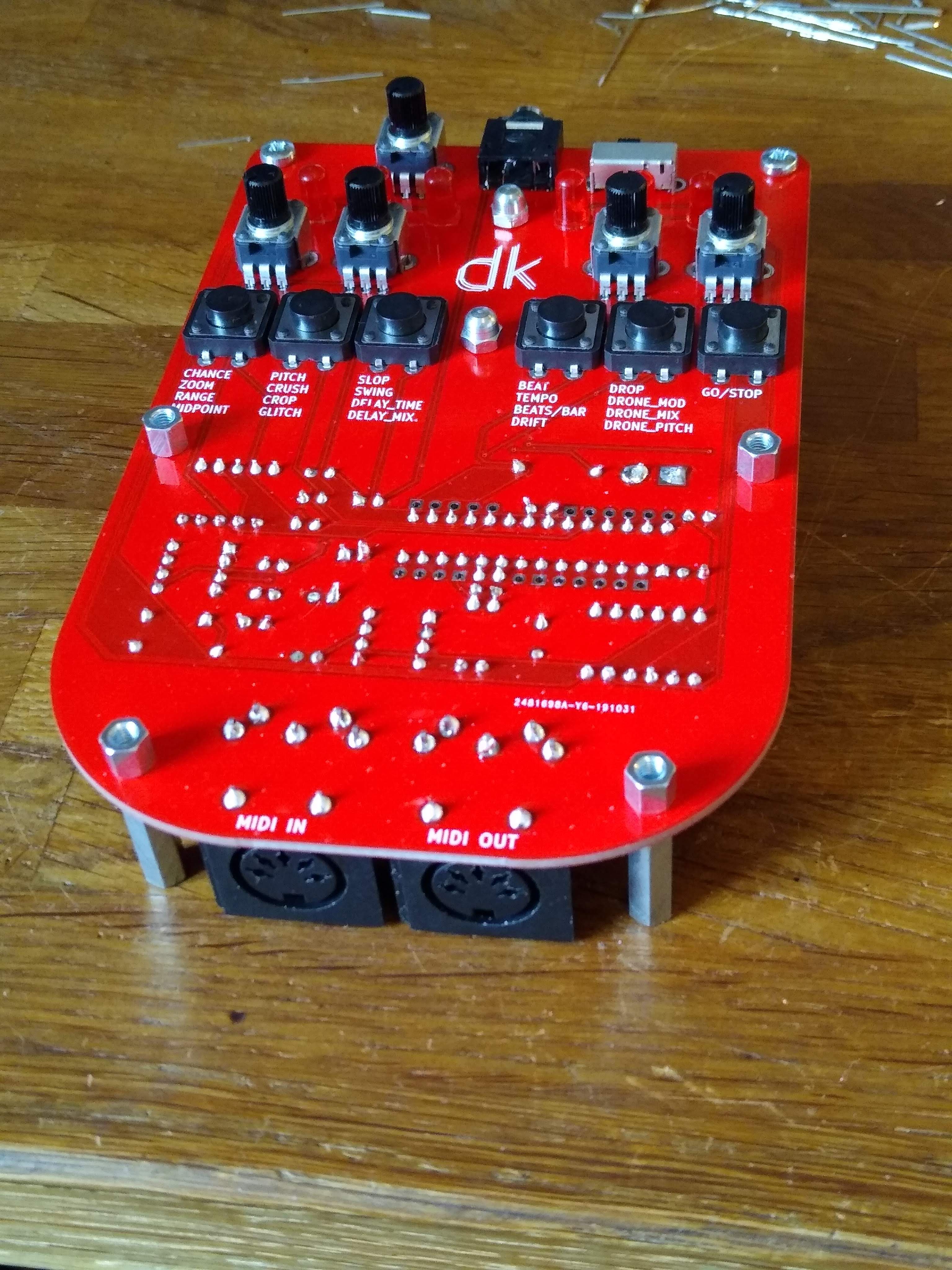
- 4 real-time control knobs
- 16 controllable parameters
- Save/load function
- Tap tempo
- 3.5mm line/headphone output
- Lo-fi mono 8-bit sound
- MIDI in/out
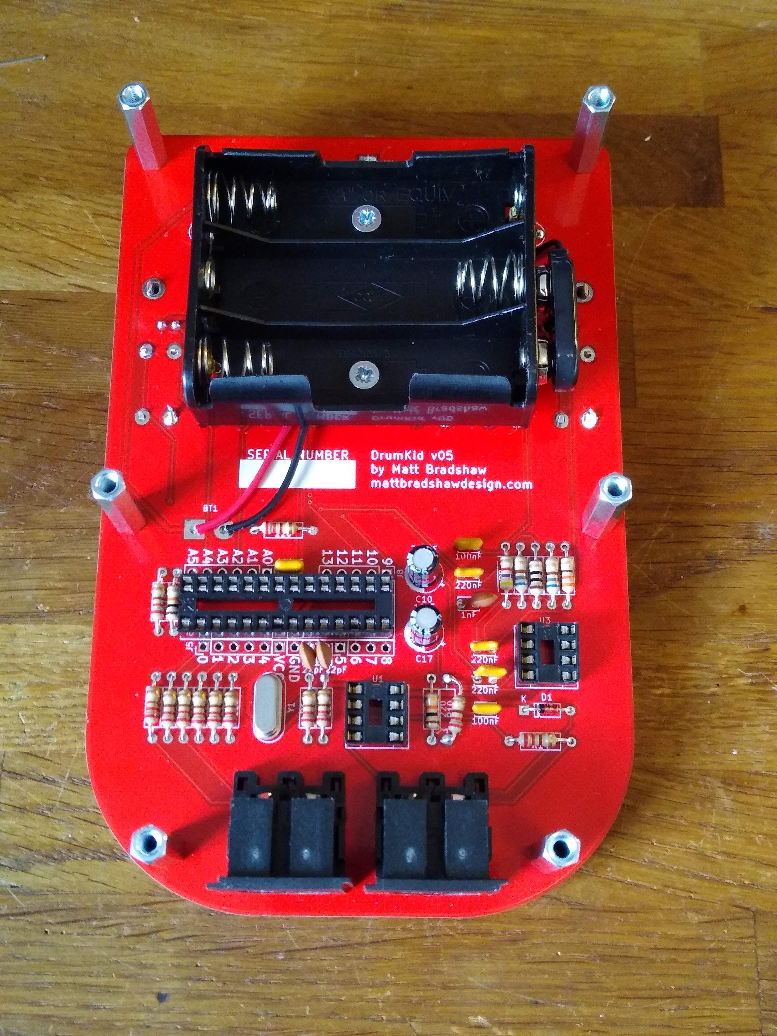
- Powered by 3xAA batteries
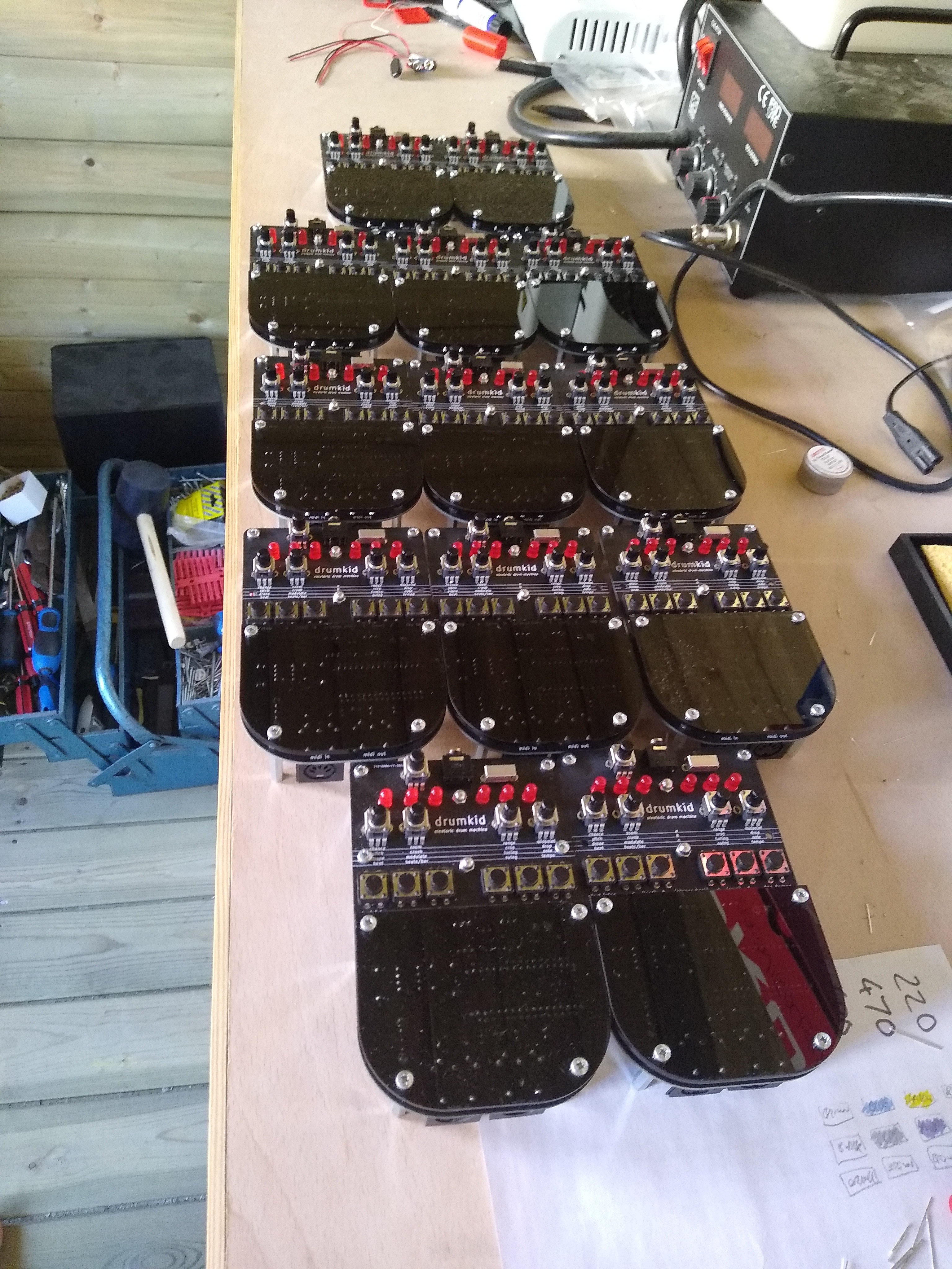
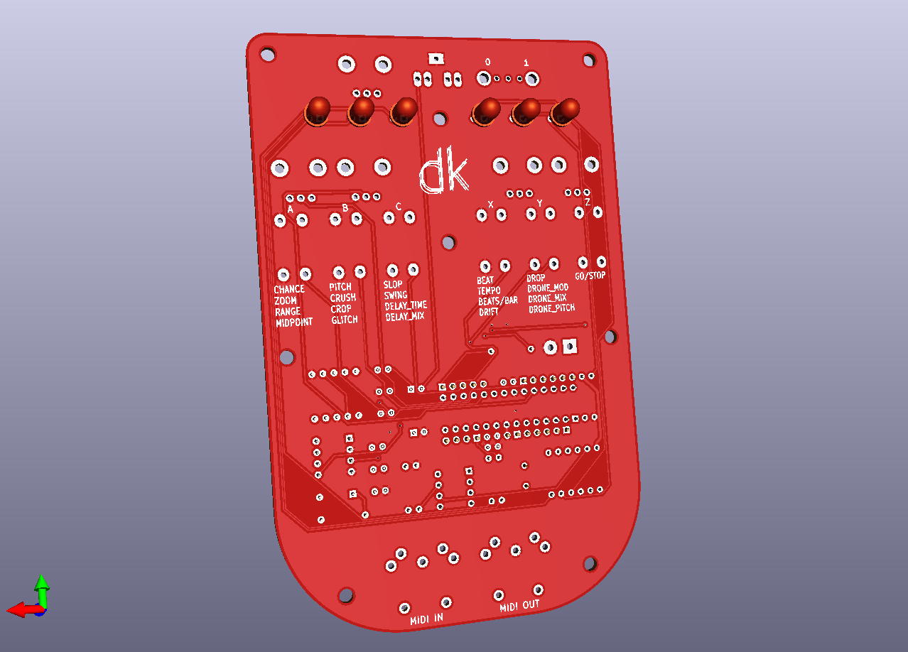
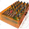
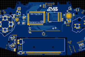
DrumKid is an open-source, hackable product based around an Arduino Nano. The final product features a minimalist design consisting of a single PCB with buttons, knobs, and LEDs mounted on one side, and all other components mounted on the other side. Two laser-cut sections are used to protect the electronics.
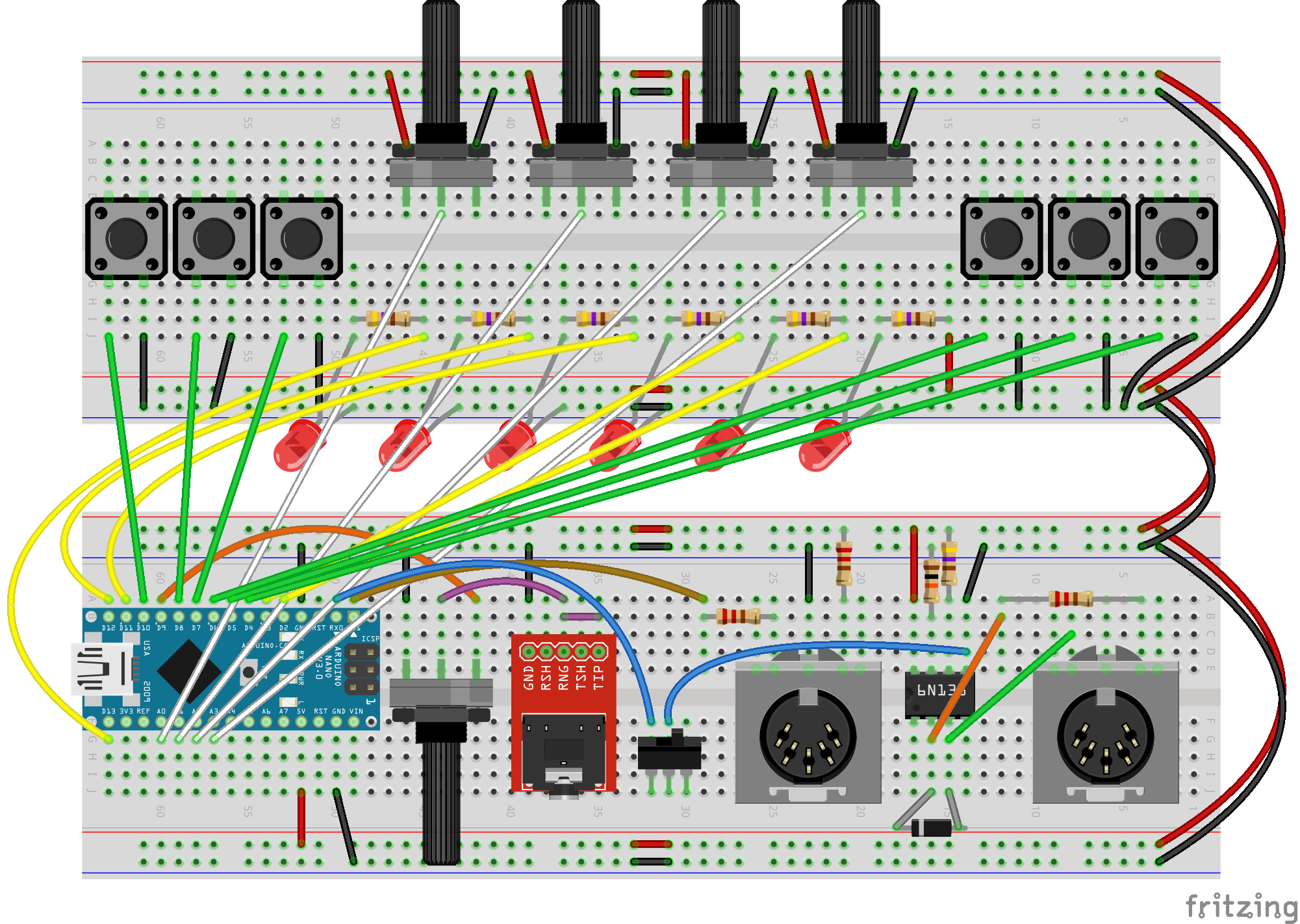
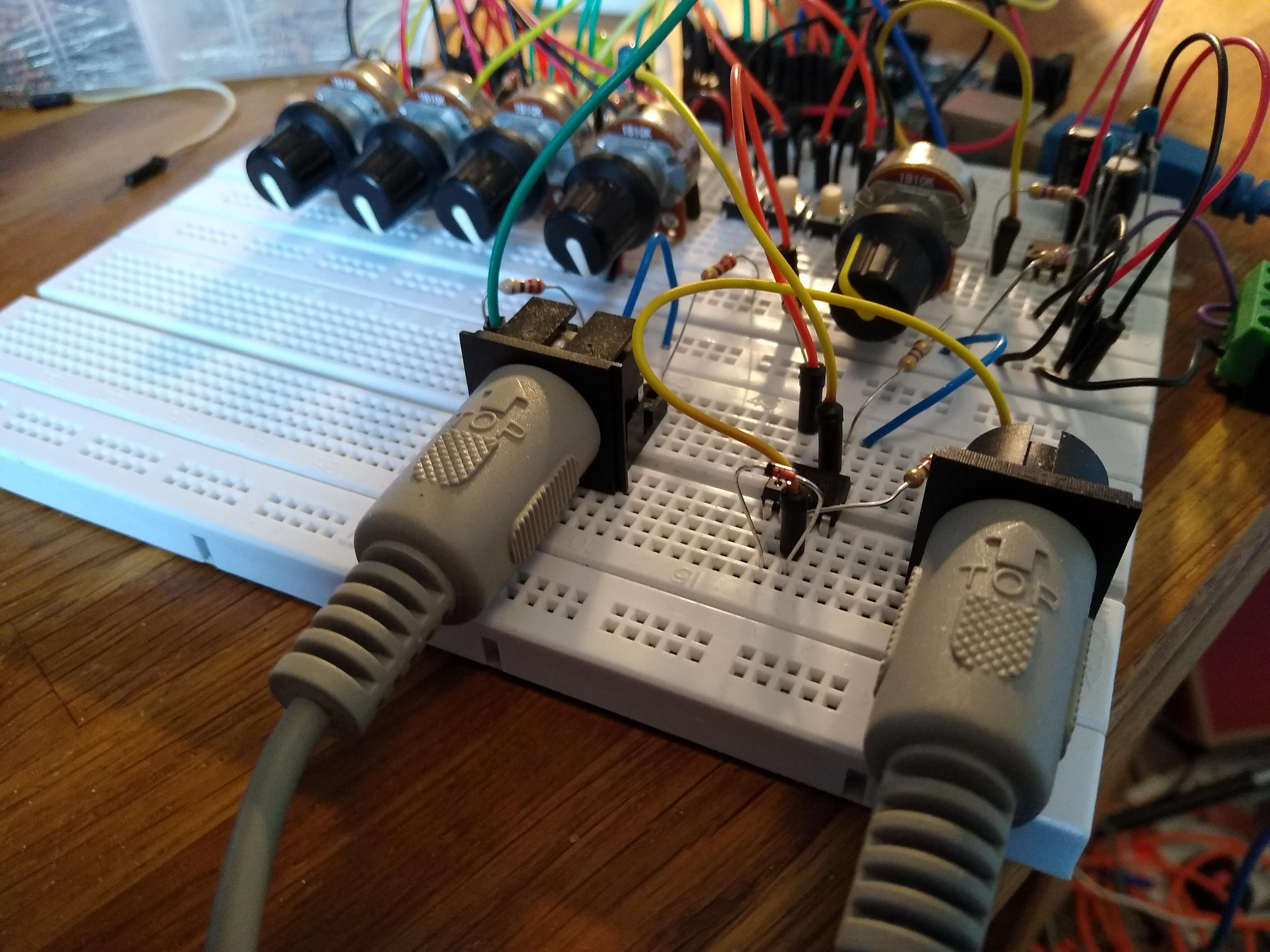
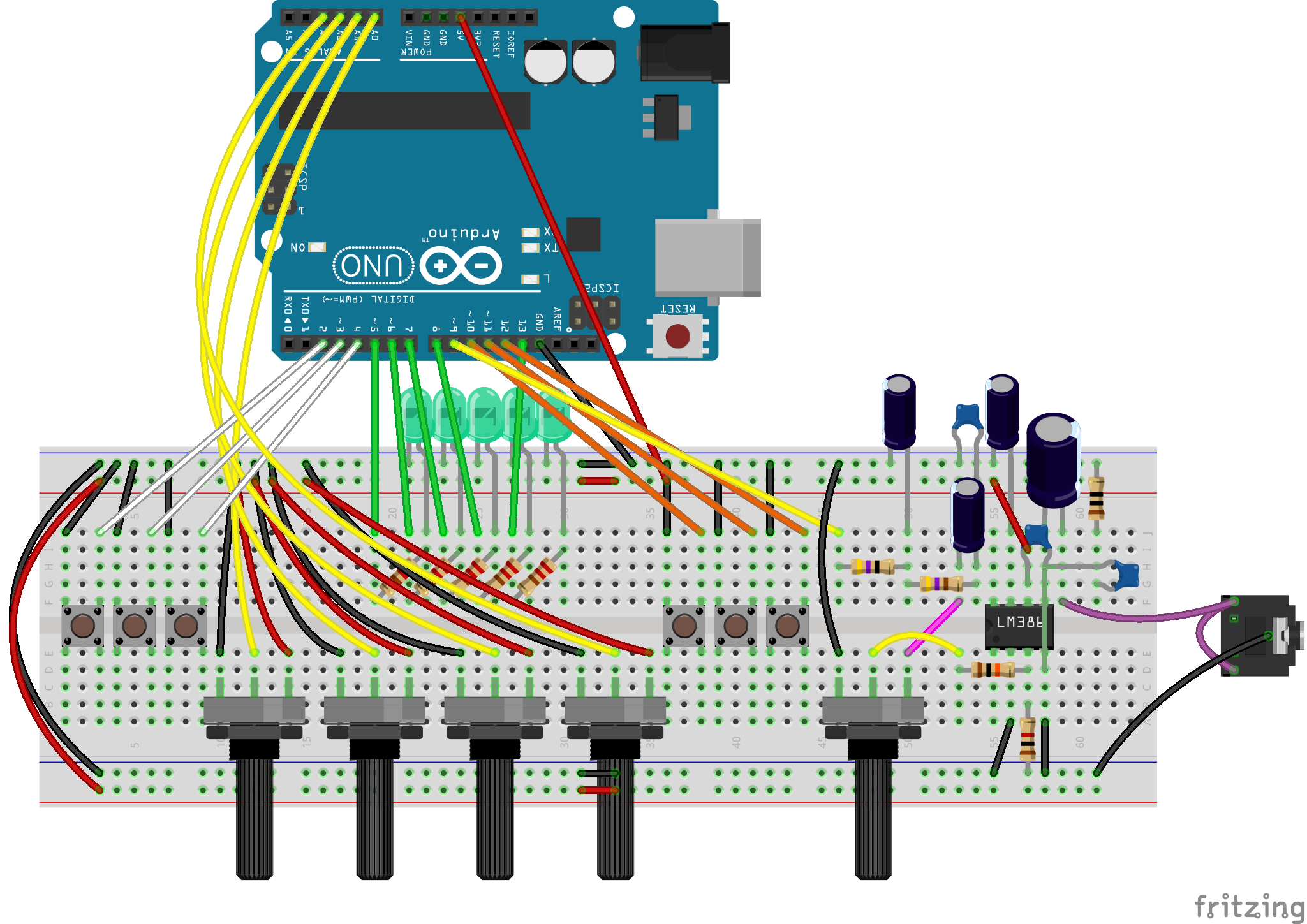
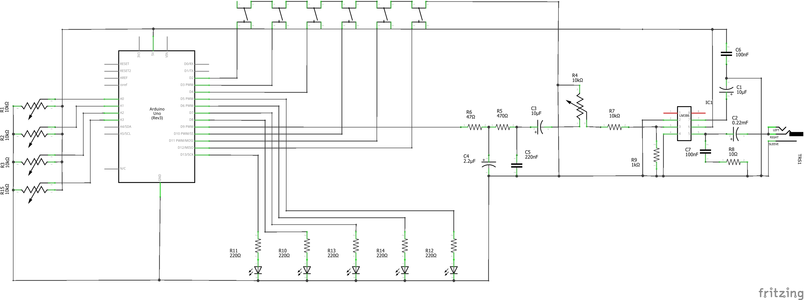
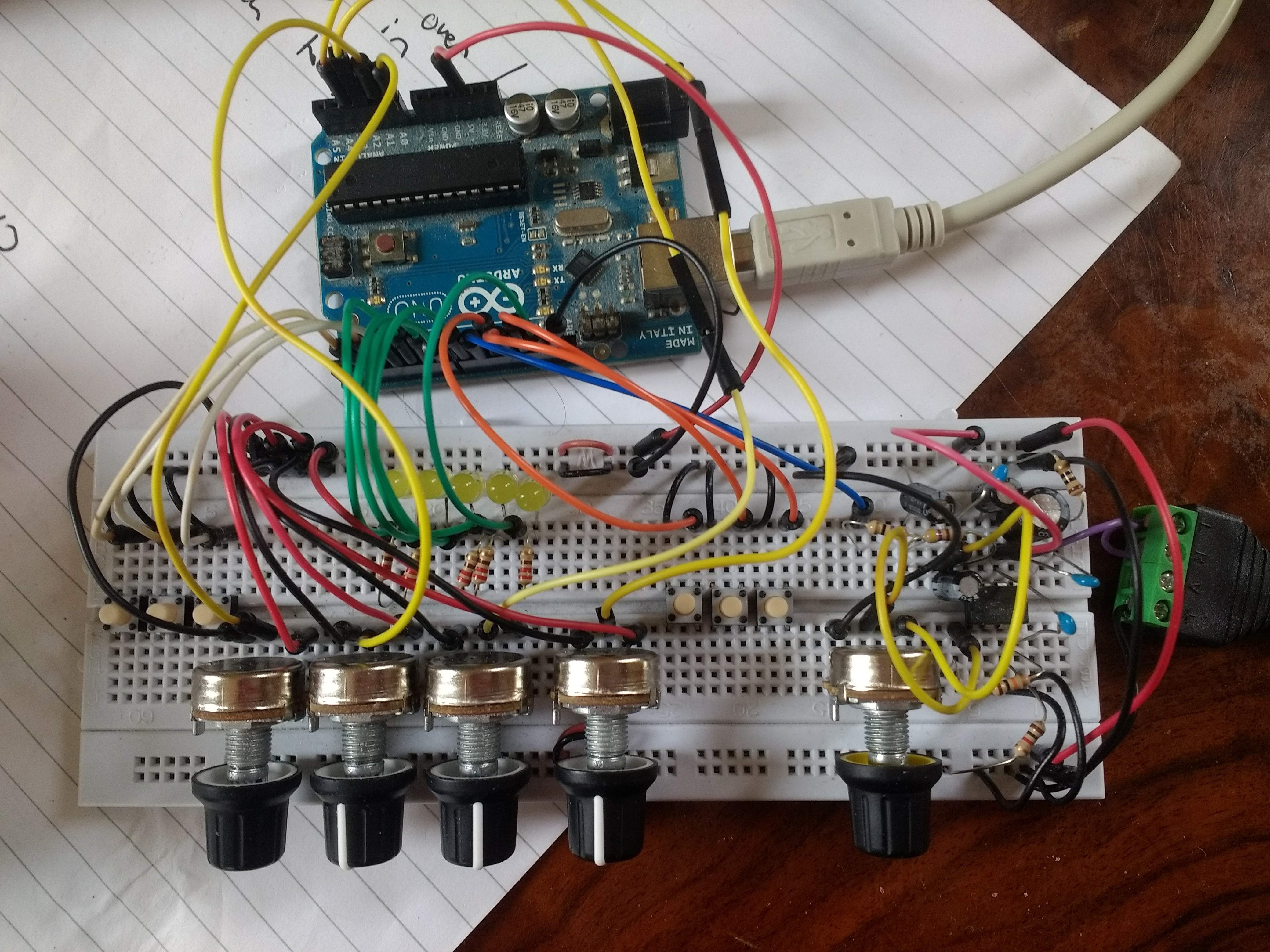
DrumKid can also be constructed as a breadboard/stripboard project using an Arduino Uno - see the build instructions for details.
All necessary files can be found on this page and/or the DrumKid GitHub repository.


 Derek F
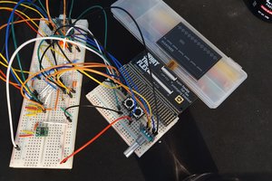
 Jay8ee
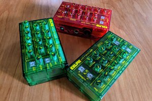
 Kenneth Marut
 dbtayl
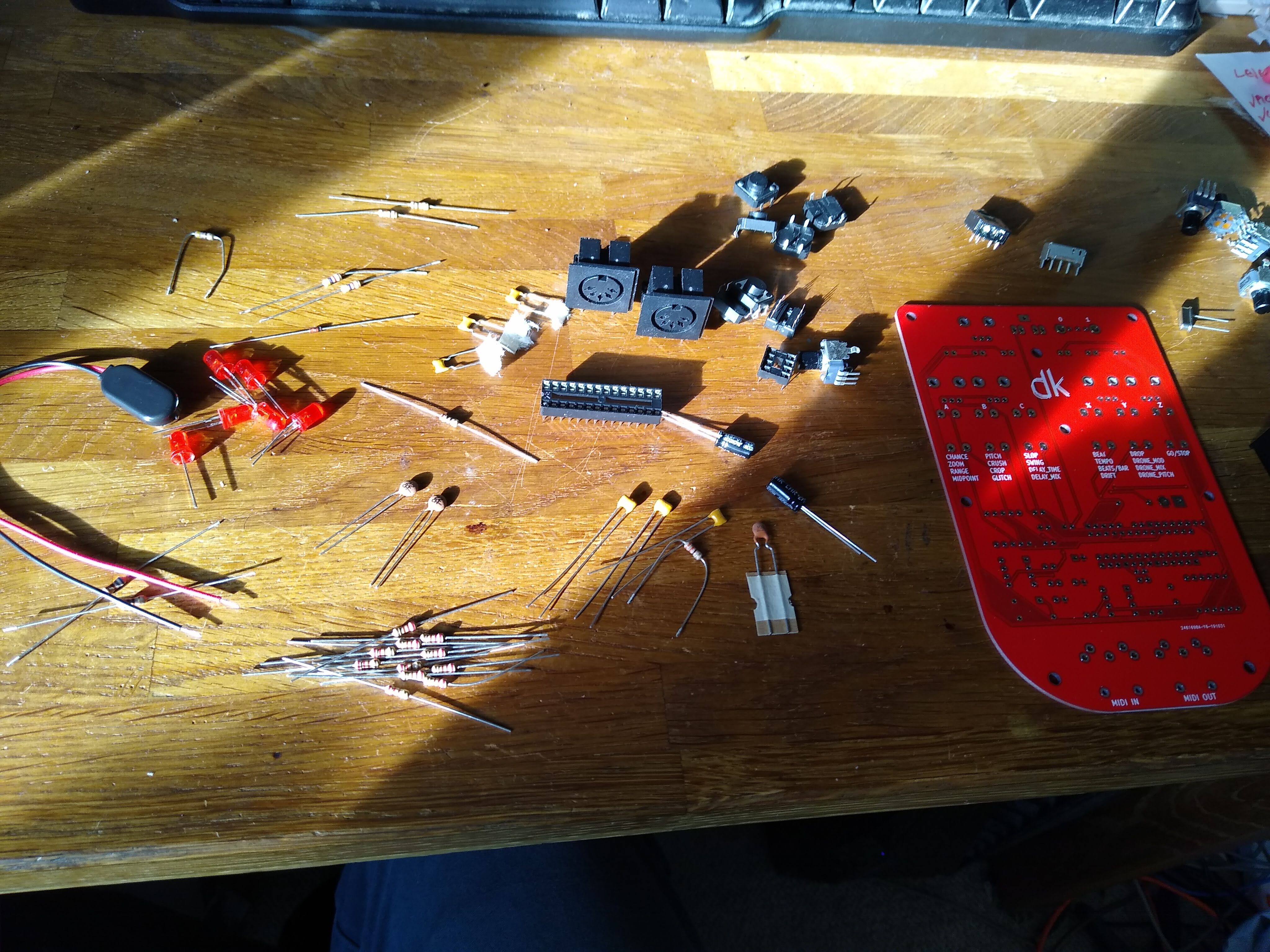
Hey, I saw github release the pcb of V10, can it be used now? Which version of the corresponding software should be used