Close
0%
0%

UV Curing Chamber

A UV light curing chamber made with an old rack, some aluminum foil, and three 50W UV LEDS. An Arduino is used as a programmable timer.

Similar projects worth following
It is well known that resin 3D printed parts need to be post cured after printing to complete the polimerization reaction of the resin. Putting the part under the sun works, but is unacceptable in a professional environment (you need to wait until there is a nice sunny day, the exposure is not controlled, it´s not perfectly repeatable, etc).
I inspired the build on a commercially available chamber: the Wanhao Boxman. It uses four 30W high power LEDs to expose the prints, and a touchscreen to program a timer that controls the LEDs on-off time.
I used an old equipment rack (a Cisco Catalyst 8500) that I salvaged from the trash at my university as the structure of the chamber. An Arduino is used as a programable timer, and the light power is provided with three 50W, 405nm LEDs, whose wavelenght falls into the UV-A spectrum.

The design for this curing chamber was inspired by the Wanhao Boxman I chamber. It is a commercially available chamber that uses four 30W UV LEDs as light sources.

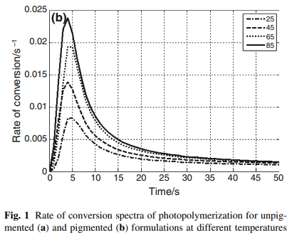
Another additional use for this chamber is found in UV glue curing, a function in which this chamber offers great performance because of the high total LED power (150W total). Very short curing times can be achieved. This is what motivated the entry of this project to the Hackaday Prize 2020, in the Field Ready open challenge. This curing chamber design allows for a very economical build of a high power UV glue curing device, made from readily available components and low-cost manufacturing methods.

In the following video I summarize the project:

The idea with my curing box was to surpass the light power of the Boxman I, while keeping it under the price of Boxman I. 

For the structure of the chamber, I used an old Cisco Catalyst 8500 rack that I salvaged from the dumpster at my university. Without the equipment, the rack is just a very nice and sturdy box. The inner walls need to be reflective in order to get the most uniform curing possible. Regular mirrors are a poor choice, since the glass in front of the reflective material absorbs UV light. A better solution (and a lot cheaper) was to cover the inner walls with cardboard sheets with aluminum foil glued on. This reflects almost all the incident UV light. 

Rack interior
The interior of the rack. The back board was also removed
Rack interior with aluminum reflectors
This shows the interior of the rack already covered with the front surface "mirrors" (they are cardboard with glued aluminum foil)

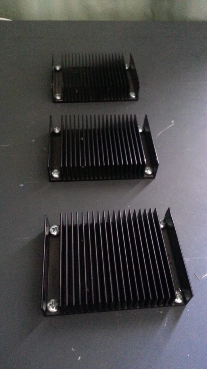
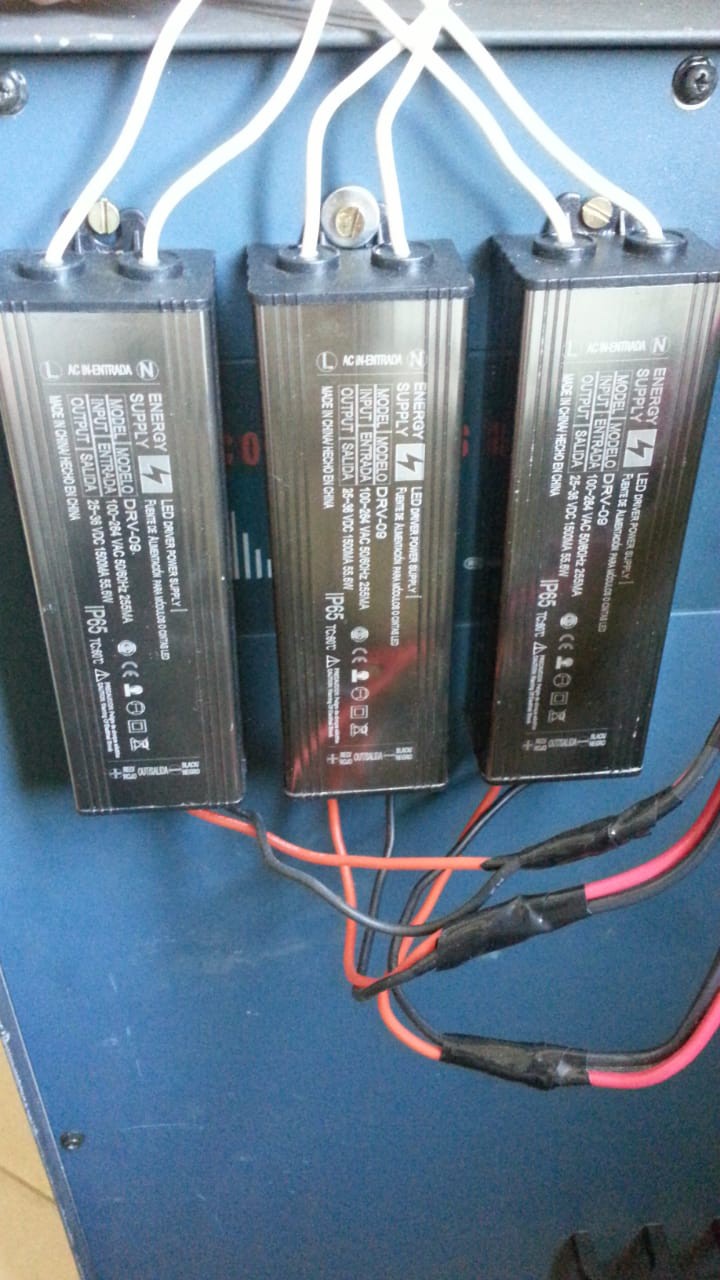
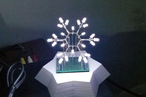
The light sources are three 50W, 405nm UV LEDs. These need to be attached to a heat sink because they dissipate a substantial amount of heat. To drive them, I used three 55.6W LED drivers (one for each LED).  Three holes were cut on the top of the chamber with an angle grinder to accommodate the LEDs.

50W LEDs as delivered
The 50W, 405nm LEDs as delivered
LEDs installed inside of the rack
The 50W LEDs installed inside the rack


I needed a timer to control the exposure time, that turned on the LEDs and turned them off after the programmed time had passed. For this, I used an Arduino Nano, a relay module, some pushbuttons and a 16x2 LCD display. The code for the Arduino (included down below) is based on the very nice Kitchen Timer project, adding some lines of code to control the relay (which in turn switches mains voltage to the LED drivers), and a greeting screen on the display when the system is turned on. The circuit schematic is very similar to the aforementioned project. 

The circuit is designed to be easily built with perfboard. The board layout included was used to predesign the circuit with the perfboard construction in mind, but the same files are useful if etching a copper clad board. Power is provided using a 220/12V transformer with a full bridge rectifier that I salvaged from an old wall wart. This is further regulated with a 7809 linear reg on the board, which in turn powers the Arduino. 

Backside of the controller board
Backside of the controller board. The perfboard construction is very inexpensive, demanding only a little skill at soldering.
Schematic of controller board
This is the schematic for the controller board, made in Eagle.
Orientative layout
This layout was made in Eagle and is just a guide to make the perfboard prototype. The blue traces have to be made with jumpers.

An enclosure for the electronics was designed and 3D printed in PLA using a conventional FDM 3D printer. The STL files are included in this project page.

3D model of the controller box
The 3D model of the controller box.
Interior of the control box
The interior of the built control box. The wall wart transformer is fitted inside a small casing to isolate it from the rest of the parts

Inside the chamber, the printed parts are submerged in a big flask full of water, since contact with Oxygen inhibits the polymerization reaction and thereby requires longer curing times.

Further development may include adding fans to the heatsinks, since after 3 minutes of operation the LED's get really hot. The water in which the parts are submerged...

Read more »

general_dimensions.pdf

A simple sketch with the chamber's general dimensions, including the size and position of the cutouts for the LED's

Adobe Portable Document Format - 44.74 kB - 10/05/2020 at 01:08

Preview
Download

STL.rar

STL files to 3D print the case

RAR Archive - 90.56 kB - 08/29/2020 at 00:58

Download

ino - 9.90 kB - 08/29/2020 at 00:38

Download

UV_curing_chamber.rar

Eagle circuit design files

RAR Archive - 25.83 kB - 08/29/2020 at 00:37

Download

  • 1 × Arduino Nano
  • 1 × LM7809 linear regulator
  • 1 × 16x2 parallel LCD
  • 1 × 2 relay module - 12V coils
  • 1 × 220-12V transformer with bridge rectifier In this case this was obtained from a wall wart

View all 11 components

  • Drawing with general dimensions uploaded

    Andrés Lopez Pulzovan10/05/2020 at 01:12 0 comments

    I uploaded a drawing with the chamber's general dimensions, including the cutouts for the LED's.

  • Project video uploaded!

    Andrés Lopez Pulzovan10/04/2020 at 22:13 0 comments

    I have uploaded a video showcasing the project for the 2020 Hackaday Prize:

  • A solution to the oxygen inhibition problem

    Andrés Lopez Pulzovan10/04/2020 at 18:27 0 comments

    As discussed in a previous project log update, a way to solve the oxygen inhibition problem (other than just curing for longer times) is to remove oxygen from the surface of the part. An easy way of doing it is to submerge the part to be glued in a flask of water, if the bond and glue allow it. 

    A further reduction of the curing time can be achieved if the water is heated (with an inexpensive mains water heater for example) to accelerate the curing reaction.

    Curing chamber with flask


    The curing chamber with a flask of water
    Water heater
    An example of the proposed water heater (source: Aliexpress)

  • Tidying up of project details

    Andrés Lopez Pulzovan10/03/2020 at 16:47 0 comments

    Some small tidying up of the project details. Added captions to the figures and now they open in a new tab.

  • The problem with Oxygen Inhibition

    Andrés Lopez Pulzovan10/03/2020 at 14:34 0 comments

    Oxygen inhibition is a constant problem with UV glues and resins. When the glue or resin is exposed to oxygen, it can diffuse in the superficial layer of the glue or resin and inhibit the polymerization reaction. This results in a tacky surface layer, even after curing for the specified time. 

    In my case, given that I originally developed this chamber to cure resin 3D prints, this surface tackiness was absolutely inadmissible. The "brute" solution to this problem is to cure harder and longer, that is, to use more UV light power and/or cure for longer times.

    Of course, this is an inefficient approach. A more efficient way of preventing oxygen inhibition is to... well... exclude oxygen from the surface. With resin 3D prints, what I did is to submerge the part in a big transparent flask (without the lid) full of water. It is important that the flask has a big opening, since glass can absorb a substantial amount of UV light. 

    Additionally, the water in the flask can be heated to further accelerate the polymerization reaction. A good temperature for curing is 65ºC, as can be seen in the following figures, that were taken from Kardar et.al.:

    Of course, the highter the temperature, the better, but in the case of standard UV resin, temperatures higher than 70ºC can have adverse effects on the material. 

  • A quick note about wavelengths and additional uses of the chamber

    Andrés Lopez Pulzovan09/17/2020 at 04:35 0 comments

    The wavelength selected for the LEDs of the chamber is 405 nm, because that is the wavelength required to cure most 3D printing UV resins, which in turn is the same as that of most UV curing adhesives. These wavelengths correspond to the UVA range, which represents the most "benign" range for human health.

     If a different wavelength is required, it is enough to replace the LED's with a set of the correct wavelength, making this project very versatile. A correct matching of the required wavelength of the glue or resin will improve cure times dramatically.

    If available, using shorter wavelengths (in the UVC domain) can provide an additional use of the chamber as a sterilization chamber. 

  • A detail about LED heatsinks

    Andrés Lopez Pulzovan08/29/2020 at 15:18 0 comments

    Heat sinking on CoB LEDs is critical, because the dissipated heat is substantial and the junction voltage of these LEDs drifts depending on temperature. In this case I used three heat sinks that were salvaged from the same devices extracted from the rack, and they have proven insufficient, because the temperature rise after 3 minutes of continuous operation is unacceptable. Fans will be added to improve heat dissipation

  • Arduino sketch uploaded!

    Andrés Lopez Pulzovan08/29/2020 at 15:13 0 comments

    The Arduino sketch was uploaded to the project page! As mentioned in the project's details, it is heavily based on the Arduino Kitchen Timer project (linked in this project's details) and in the code. The modifications were made to actuate the relay when the timer is started, and turn it off when time runs out (or the timer is manually stopped).

  • STL files uploaded!

    Andrés Lopez Pulzovan08/29/2020 at 15:04 0 comments

    The files to 3D print the case were uploaded to the project page! The 16x2 LCD and the relay board should fit right away. Note there is a square perimeter: the (disassembled) wall wart transformer + the rectifier are fitted there to provide isolation.

  • LED drivers installed

    Andrés Lopez Pulzovan08/29/2020 at 14:59 0 comments

    The three 55.6W drivers were installed. They connect to the mains through the relay, so that the LEDs are turned on or off by connecting the drivers to the mains.

View all 10 project logs

Enjoy this project?

Share

Discussions

Similar Projects

Does this project spark your interest?

Become a member to follow this project and never miss any updates