0%
0%
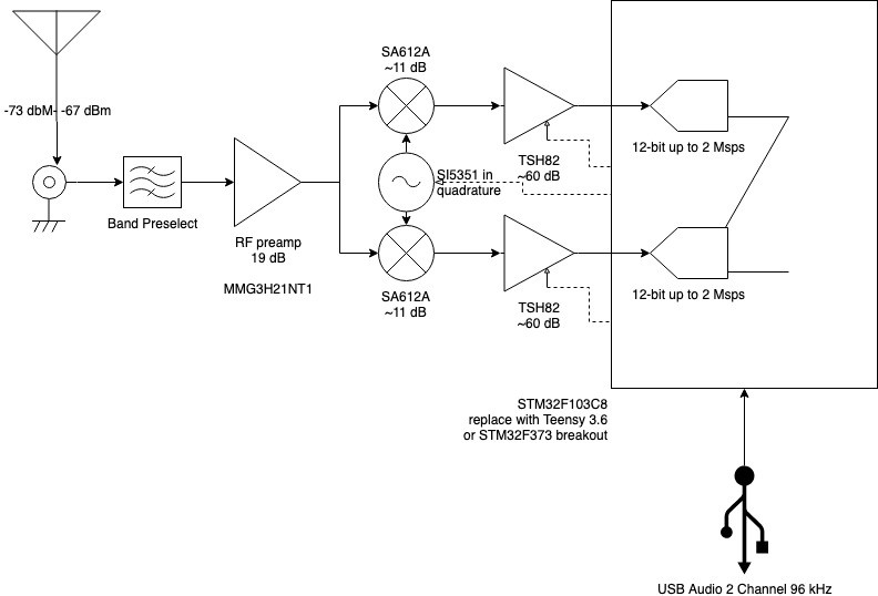
K8TRC Digital SDR
A software defined radio transceiver designed for digital modes, primarily WSPR and FT8 on HF.
 Trevor R.H. Clarke
Become a Hackaday.io member
Already have an account? Log in.
Just one more thing
To make the experience fit your profile, pick a username and tell us what interests you.
Pick an awesome username
hackaday.io/
Your profile's URL: hackaday.io/username. Max 25 alphanumeric characters.
Pick a few interests
Projects that share your interests
People that share your interests

 W5VO
W5VO
 Nick Sayer
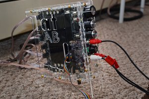
 tshen2
Cool! I'll be watching this for my "$50 Ham" series. RTL-SDR projects are great, but building an SDR from scratch would be fantastic.
By "sampled chips", do you mean chips you've gotten for free by asking for a sample?