 Dewet
DewetNOAH Baseboard
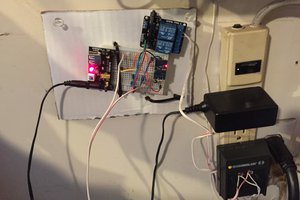
The GSM controller that came with my gate motor when I bought my house recently decided to give up the ghost. Now I could go out and buy a replacement unit but where is the fun in that. So with a bit of time spent and some parts lying around waiting for a project I decided to design my own controller for the garage and gate.
Now the new controller will not have its own GSM module as I already have a few tied into my existing home automation system and will be using a call from them to trigger the gate. However, I have been itching to try out a Telegram/MQTT/Wireless control chain as part of something else I am working on so thus the MQTT NOAH Baseboard was born.
This unit had to fulfill the following requirements:
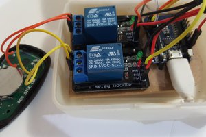
- 5 x Relays (Gate01, Gate02, Garage Door, Garage Light and one Optional)
- 5 x Inputs (Common ground as most gate and garage controllers use this output)
- 5V Supply (Fed from a power bank for easy backup power)
- Fit the ESP8266 NodeMCU module
- MQTT controlled
- Wireless
A very important note: NEVER RELY ON WIRELESS FOR CRITICAL CONTROL. You don't want to be stuck in a situation where you are unable to open/close/receive alerts because your neighbor decided to connect a telecoms level wireless transmitter and point it at your house.
These things should be connected using wires, but since I have backup remote controls and enterprise-grade WiFi covering my yard I thought what the heck, this unit will be wireless. Guess in this case I am actually the neighbor with the telecoms equipment mmm..., but I digress.
Software Needed:
- Arduino IDE
- Installed ESP8266 board library for NodeMCU
- Installed PubSub library (Thanks knolleary)
- Working MQTT broker (Any of the following: CloudMQTT, Mosquito, Adafruit MQTT)
- MQTT.fx
Control
The unit is controlled by subscribing and publishing to a set of MQTT topics. For the purpose of this post I will not go into detail about how MQTT works, there are brilliant videos on the internet that do an excellent job.
If you want to test the unit, change your Arduino sketch to include your WiFi credentials and MQTT broker. Then publish a 1 to the SET topics below to trigger the relays. Monitor the STATUS topics for the state of the input pins.
My topics work as follows:
- GARAGE/GATE01/STATUS
- GARAGE/GATE01/SET
- GARAGE/GATE02/STATUS
- GARAGE/GATE02/SET
- GARAGE/DOORV/STATUS
- GARAGE/DOORV/SET
- GARAGE/LIGHT01/STATUS
- GARAGE/LIGHT01/SET
- GARAGE/OPTIONAL/STATUS
- GARAGE/OPTIONAL/SET
- GARAGE/MOVEMENT/STATUS
- GARAGE/CONTROLLER/STATUS
Output Topics:
- Relay 1 - GARAGE/GATE01/SET
- Relay 2 - GARAGE/GATE02/SET
- Relay 3 - GARAGE/DOORV/SET
- Relay 4 - GARAGE/LIGHT01/SET
- Relay 5 - GARAGE/OPTIONAL/SET
Input Topics:
- Input 1 - GARAGE/GATE01/STATUS
- Input 2 - GARAGE/GATE02/STATUS
- Input 3 - GARAGE/DOORV/STATUS
- Input 4 - GARAGE/DOORN/STATUS
- Input 5 - GARAGE/MOVEMENT/STATUS
I will go through detailed notes on setting up everything in the logs below on this project.
- Build, connect, control!
 Pete Hoffswell
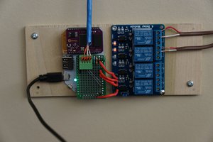
 James Harding
 Alexander Else