 Maksim Surguy
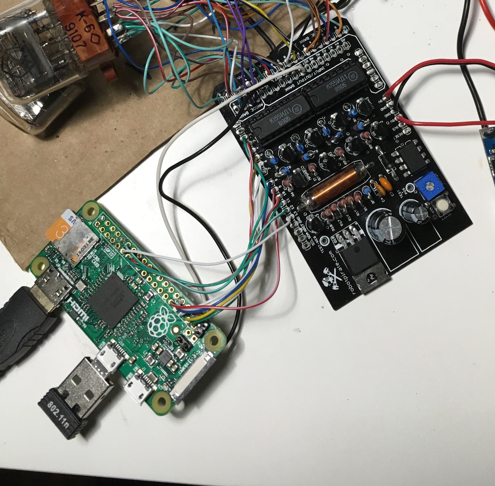
I wanted to build a Nixie clock by combining Raspberry Pi Zero, Arduinix and 4 IN-12 Nixie tubes I bought on Ebay and putting it into a case I am designing and 3D printing.
The goal of the project is to create a great looking clock with some IoT functionality while keeping it under $100 in cost.
Possible feature additions after the basic clock is working:
- Display temperature, humidity via sensor.
- Display arbitrary number from the internet
- Timer and/or alarm functionality
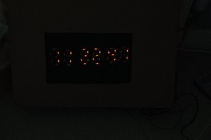
Here are the latest videos of the clock in action:
Energy consumption of this clock turned out to be much lower than I thought. It maxed out at 3.8 W displaying all four numbers and being connected to WiFI.
 daw9000
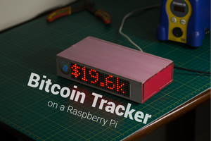
 Jonty
Jonty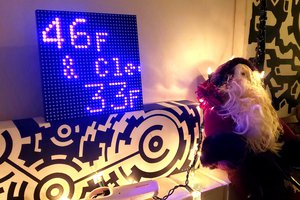
 Clay Graham
 JK
JK