 Randy Elwin
Using a dollar store solar garden light for low-power ATtiny projects is the holy grail of cheap hacks. Where else can you buy a solar cell, 300mAh NiCd battery, and a boost converter chip for $0.99?
However, harnessing the converter’s power reliably for a 2V to 5V microcontroller is a bit tricky as its output ranges from off (low battery) up to 10V. The usual approach of adding a LDO regulator or a zener diode and a cap usually works, but adds parts and may not supply a full 2V to 5V range. A more efficient and complicated circuit (link) also supports an efficient low power mode using more parts, and may not work for some types of converter chips.
A much simpler and cheaper approach is to have the ATtiny regulate its own power supply by monitoring Vcc (battery supply voltage) and controlling the converter by its solar cell input (SOL), using 1 GPIO pin. This is a simplified switched-mode power supply.
A garden light turns off its LED when the solar cell is charging the battery during daylight. At night the solar cell doesn’t charge and the converter, sensing this, turns on the LED. For this hack a GPIO from the ATtiny connected to the SOL input mimics the solar cell activity, making this a converter on/off switch.
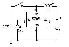
Typical garden light circuit using YX805A converter chip (this chip isn't recommended.)
Internal to the ATtiny is a way to measure Vcc using its ADC and an internal 1.1V bandgap reference, Vbg (see Microchip AN2447 for details.)
By free-running the ADC to periodically sample Vcc, the SOL output is toggled based on a selected threshold voltage. A filtering cap smoothes this bang-bang control.
In normal operation Vcc is kept close to the target voltage regardless of power draw (within the converter’s limits.) An added bonus is the threshold voltage may be lowered for a low-power mode, thus extending battery life.
Warning! Why dangerous?
When unconnected to a load the converter’s output shoots up to 10V. The filter cap retains this voltage for a few seconds to a few minutes, depending on how big of a cap is installed. Plugging an ATtiny into a hot 10V socket may damage it, or if you’re lucky, just erase part of its FLASH program. Also, bad software can kill! If the Vcc feedback control loop stops working the converter might stick in the ON state, potentially exceeding max Vcc. You’ve been warned!
Dirty Details:
- Use an ATtiny85V, the low-voltage version for best results.
- The ATtiny’s ADC is non-linear and contains measurement errors.
- The ATtiny’s Vbg reference varies between 1.0 and 1.2V, and has a small start-up delay.
- The ATtiny’s feedback loop uses the ADC. If the ADC is required for some other operation it needs to be multiplexed carefully.
- Cheap garden lights use a variety of converter chips. Not all work for this circuit. The YX8051 works ok.
Demo Circuit Using YX8051 Converter Chip:
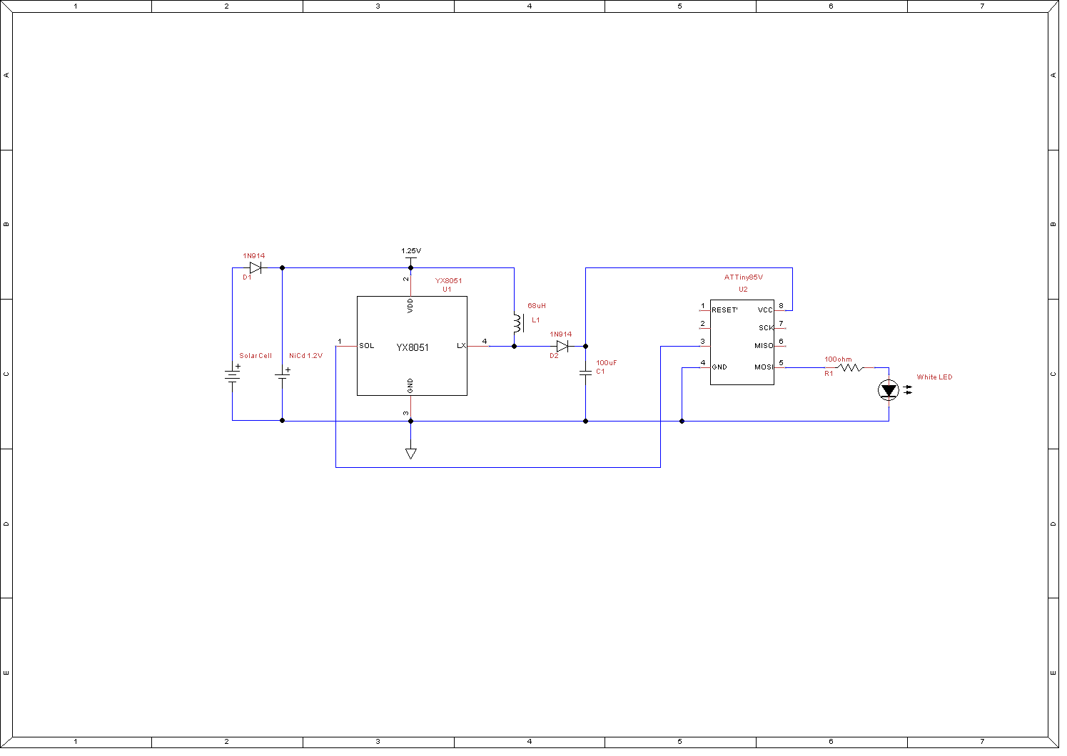
This circuit shows the mods required to use a garden light. C1 can vary but not recommended below 10uF to keep voltage swings down.
Here's a good link using these converter chips.
Here's a similar circuit (wayback machine, but missing pictures and diagrams) with some regulation. Uses the YX805. I had problems with the YX805 recovering from a depleted battery in my circuit and couldn't use it.
Arduino Code Example:
The ADC is configured for reading Vbg with Vcc ref, free-run mode, generating an interrupt every sample, roughly 630 samples per second.
In the ADC ISR the ADC value is compared to a target threshold, toggling the converter's SOL input as required. Note there's no attempt to calculate an actual voltage value (per AN2447) as we're only interested if above/below a threshold. Also note this ADC value increases for lower Vcc.
To turn off the converter, setting the GPIO on the SOL input to INPUT_PULLUP is sufficient to trigger the converter to stop output.
Hook up a voltmeter to Vcc and observe it toggle between high and low target thresholds, and how the LED responds. Using a white LED with a 2V forward voltage will turn off with lower Vcc.
/*
  Garden light demo, with Vcc regulation.

  ATtiny85V, 1mHz clock.
  Uncalibrated ADC so threshold voltages are approximate.


  PB Pins
  0 LED blinky
  1
  2
  3
  4 Converter ctl, 0 out = on; Hi-Z in, or 1 out = off.

  R. Elwin 2019. Use at your own risk!
*/


//Pin assignments PBx
const int converter_ctl = 4;
const int led = 0;

const int DELAY = 5000;
int16_t target_v;

#define Thi   150   // raw ADC value for high Vcc, around 4V
#define Tlo   550   // low Vcc, around 2V

//***************** ADC ****************

// ADC ISR triggers after conversion.
ISR( ADC_vect )
{
  int16_t v;
  v = ADCL;
  v |= (ADCH << 8);

  if ( v > target_v )  //target Vcc (ADC raw value), higher is lower V
  {
    pinMode(converter_ctl, OUTPUT);   //turn on
    digitalWrite(converter_ctl, LOW);
  }
  else
  {
    pinMode(converter_ctl, INPUT_PULLUP); //turn off, with PU
  }
}

// configures ADC for reading battery supply voltage
void ADC_autostart(void)
{
  // see table 17-3, Vcc as Voltage Reference, read Vbg
  ADMUX =
    (0 << ADLAR) |     // 1=left shift result for 8-bit, 0=10-bit
    (0 << REFS2) |     // Sets ref. bit 2
    (0 << REFS1) |     // Sets ref. bit 1
    (0 << REFS0) |     // Sets ref. bit 0
    (1 << MUX3)  |     // MUX bit 3  see table 17-4 for mux sel
    (1 << MUX2)  |     // MUX bit 2
    (0 << MUX1)  |     // MUX bit 1
    (0 << MUX0);       // MUX bit 0

  //ISR on, freerun auto-trigger, 128 prescaler, about 630sps @ 1mHz clock
  ADCSRA =
    (1 << ADIE)  |    //ISR en
    (1 << ADATE) |    //autotrigger
    (1 << ADEN)  |    // Enable ADC
    (1 << ADPS2) |    // prescaler bit 2
    (1 << ADPS1) |    // prescaler bit 1
    (1 << ADPS0);     // prescaler bit 0

  ADCSRB = 0;   //free run

  ADCSRA |= (1 << ADSC);          // start ADC, should trigger ISR
}


void setup() {
  pinMode(converter_ctl, INPUT_PULLUP); // assume C charged at boot, turn off to avoid overshoot.
  target_v = Tlo;

  ADC_autostart();  //run ADC feedback loop
  delay(100);       //let run before turning on LED

  pinMode(led, OUTPUT);
}


void loop()
{
  target_v = Thi;             //enough to power LED
  digitalWrite(led, HIGH);    //observe Vcc with meter, see if holding Vcc when LED on.
  delay(DELAY);

  digitalWrite(led, LOW);     //observe Vcc with meter, see if holding Vcc when LED off.
  delay(DELAY);

  digitalWrite(led, HIGH);    // Watch LED fade out with low-power
  delay(500);
  target_v = Tlo;
  delay(DELAY);
}