 Daren Schwenke
Using it!
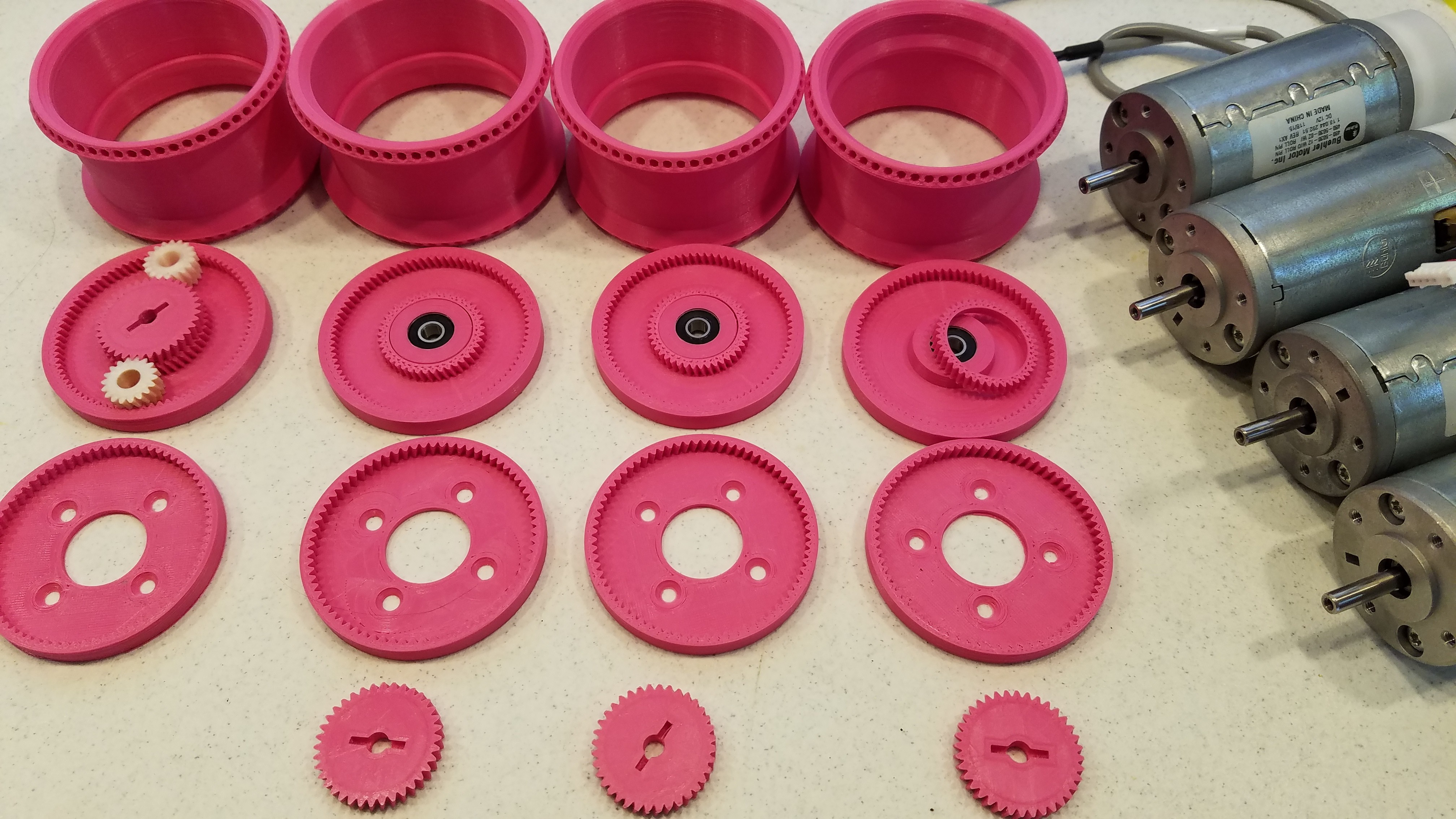
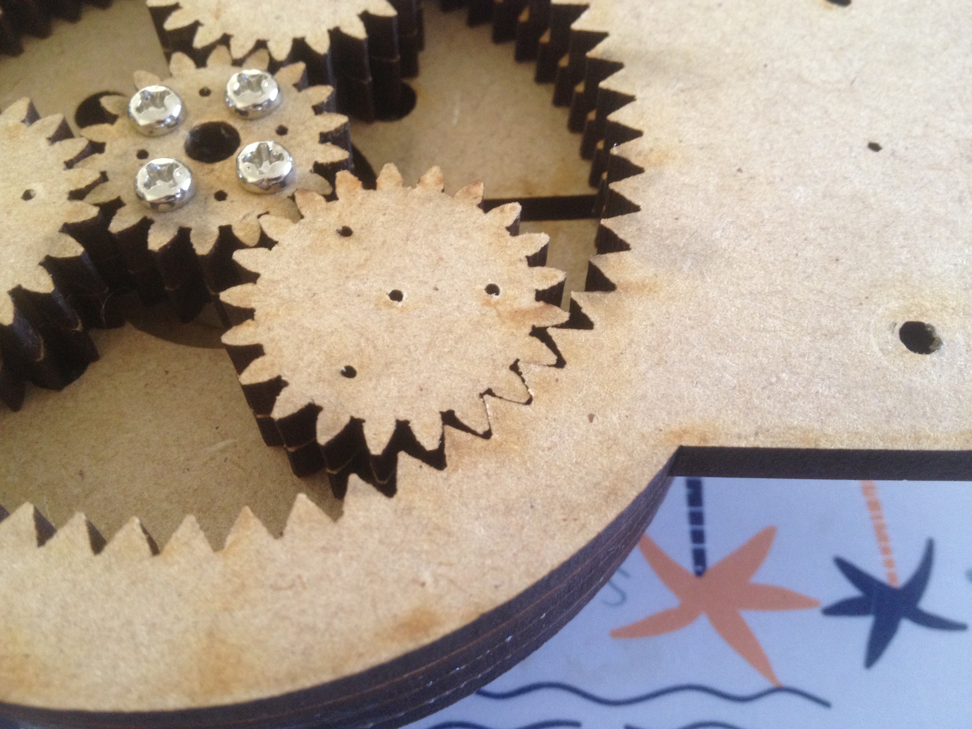
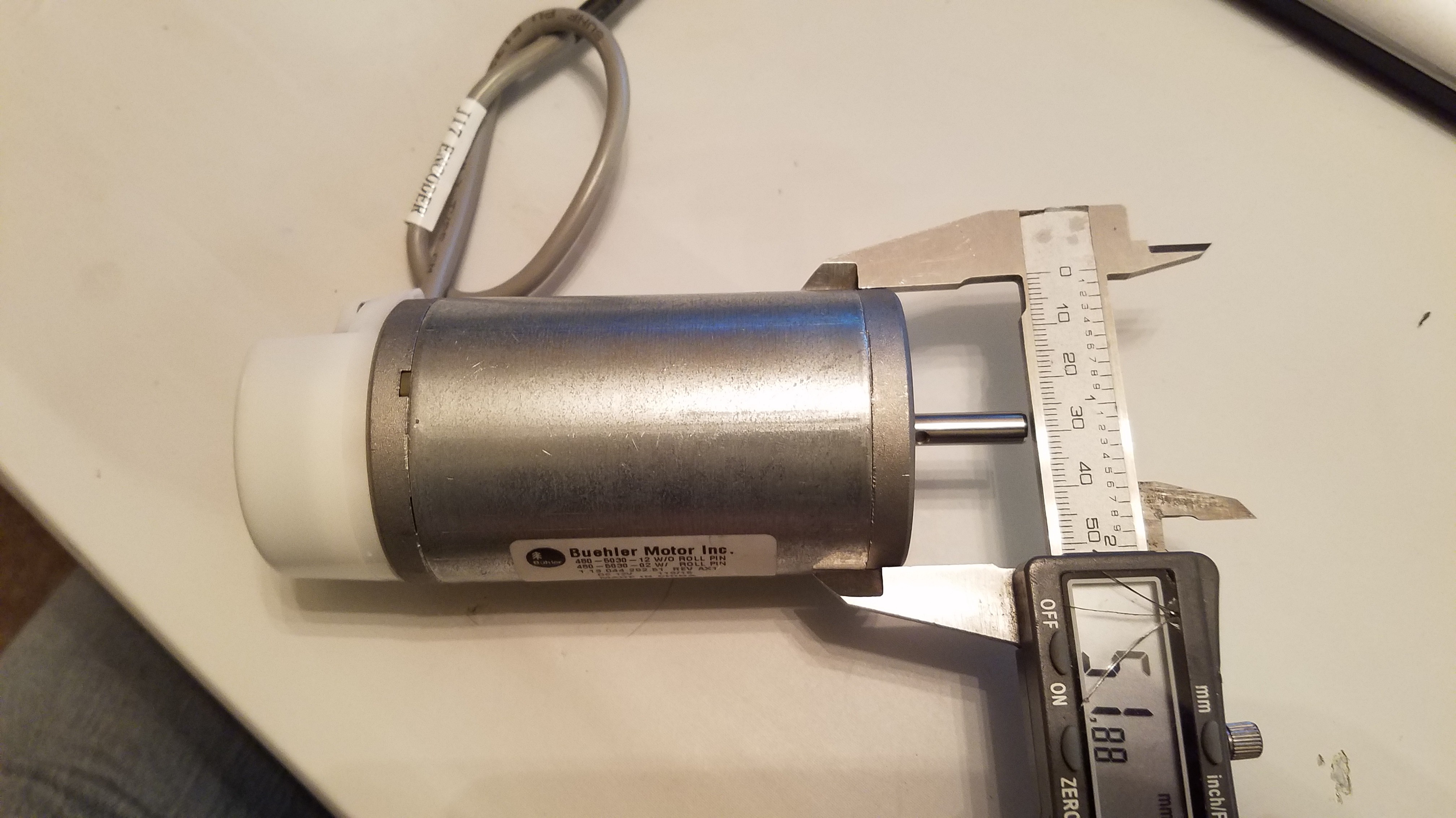
I've decided I need a transmission for testing out the #FilaMecanum concept, so this is going to be it.
Background
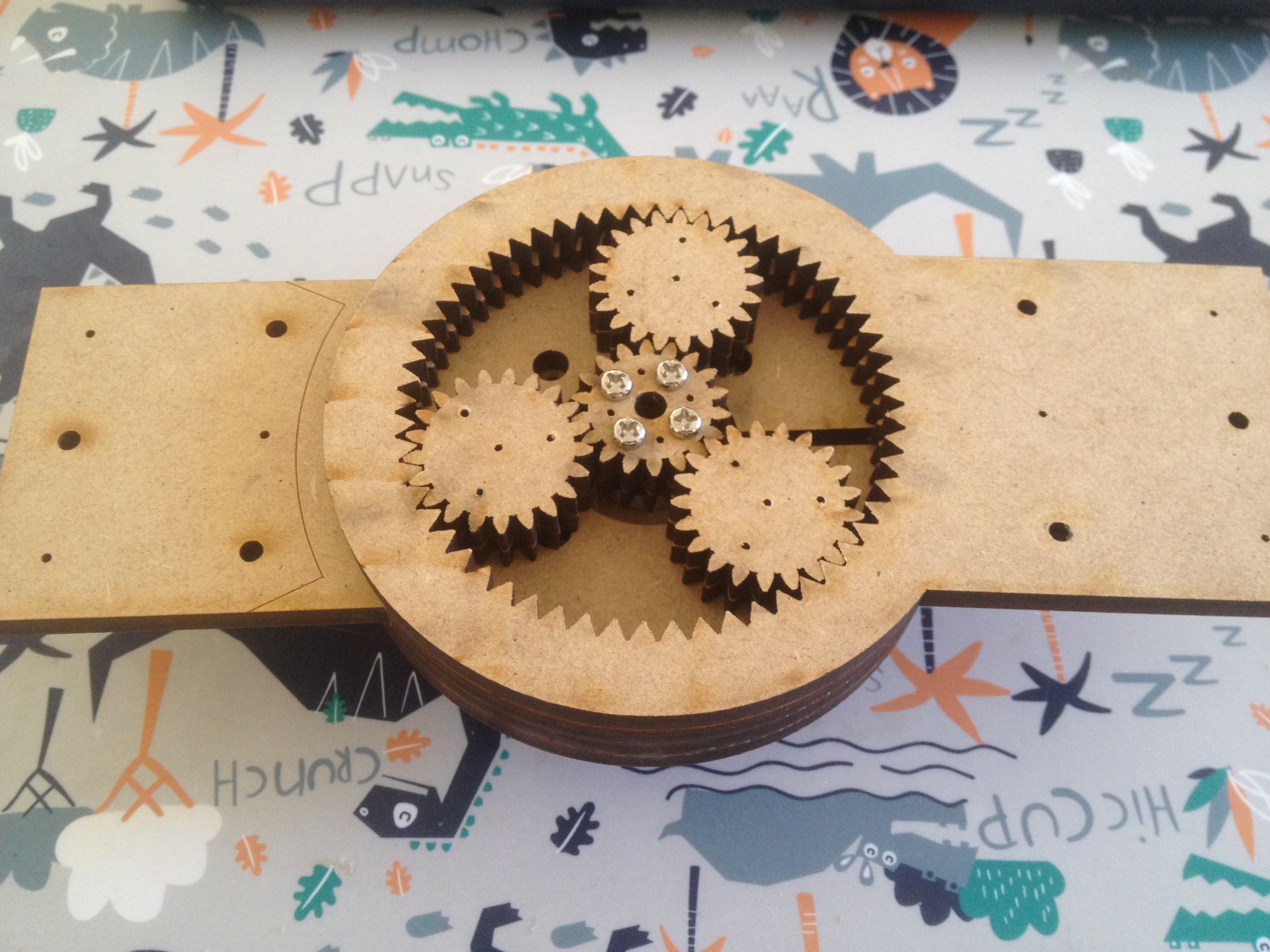
First I think I need to explain how a normal planetary drivetrain is constructed.
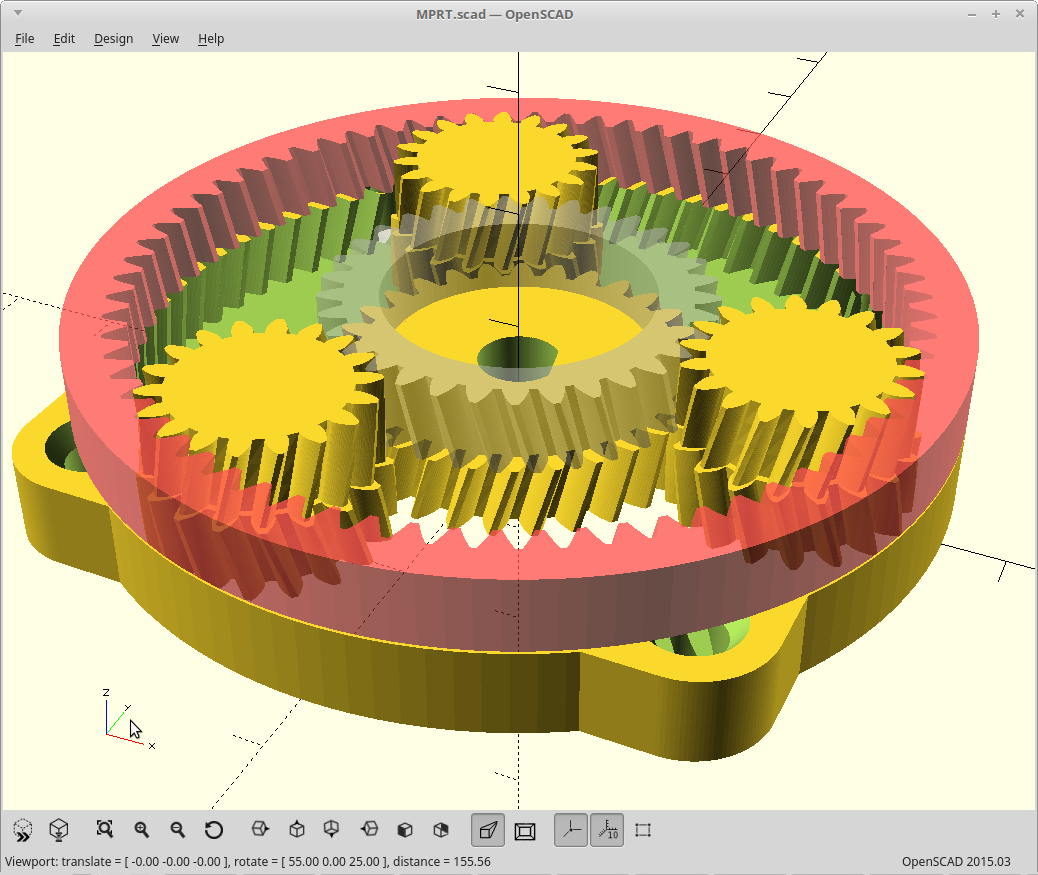
The power input turns the sun, and the sun drives the planets which rotate within a stationary ring gear. The planets are mounted to a carrier with bearings, and the carrier is where you take your output.
This arrangement gives you a gear reduction of:
To get further reduction, you can add more stages just like the above, all sharing the same ring gear. The stages multiply, so 3 stages of 3:1 would give you a 27:1 reduction. Problem here is now you need 9 planets, 9 bearings, 3 suns, 3 carriers, and 3 times the height too.
If you try to get more than about 3:1 reduction per stage, you end up needing fine teeth and a small sun gear. Small sun gears don't survive very long unless made of some heavy duty stuff and so 3D printing/laser cutting that doesn't work so well.
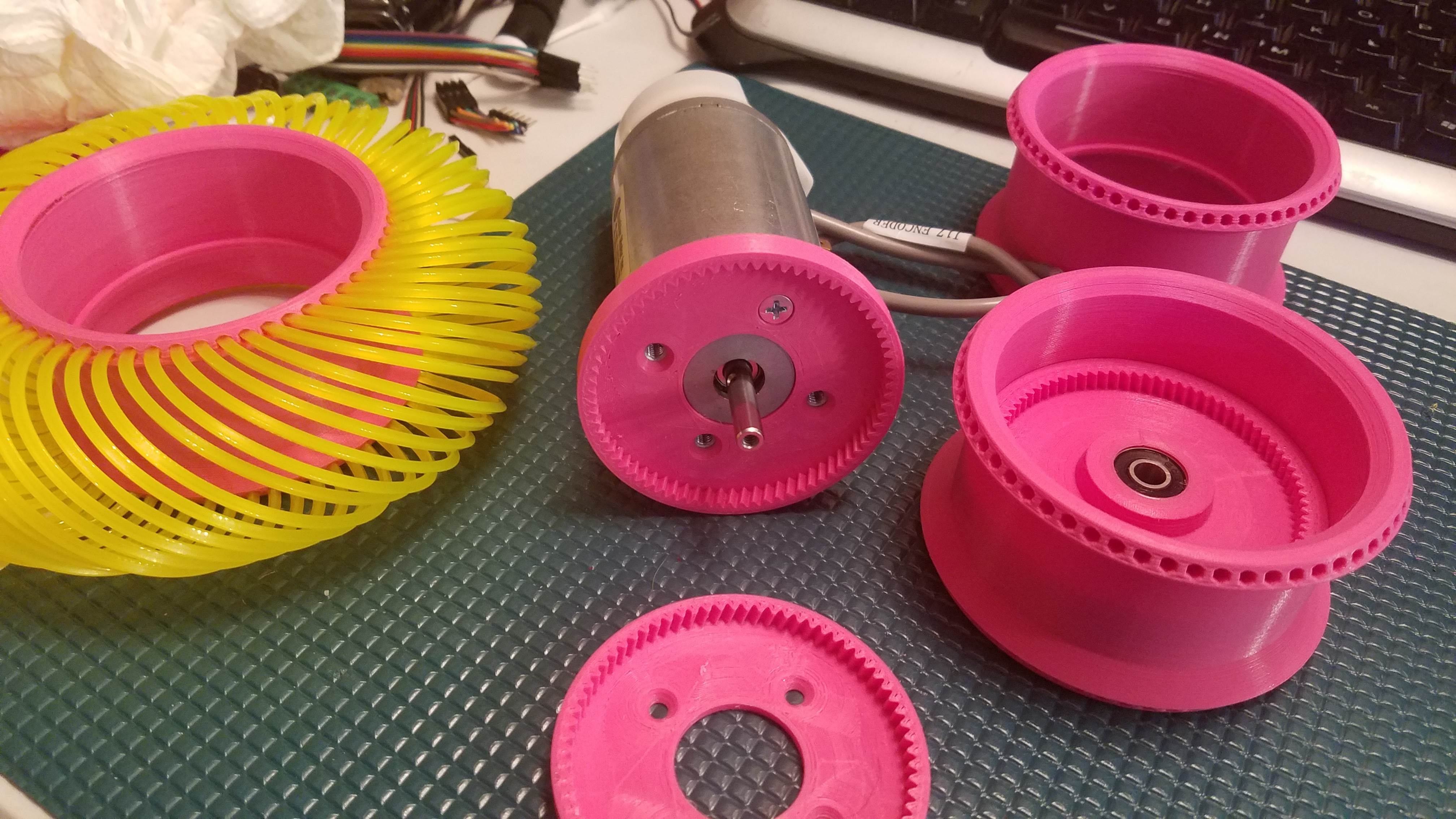
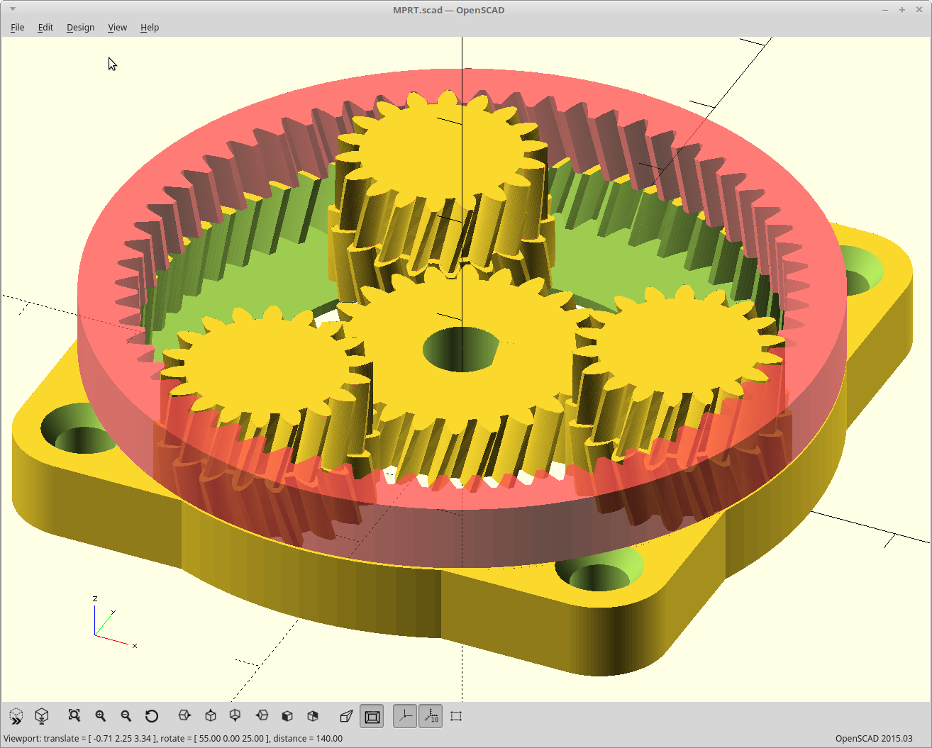
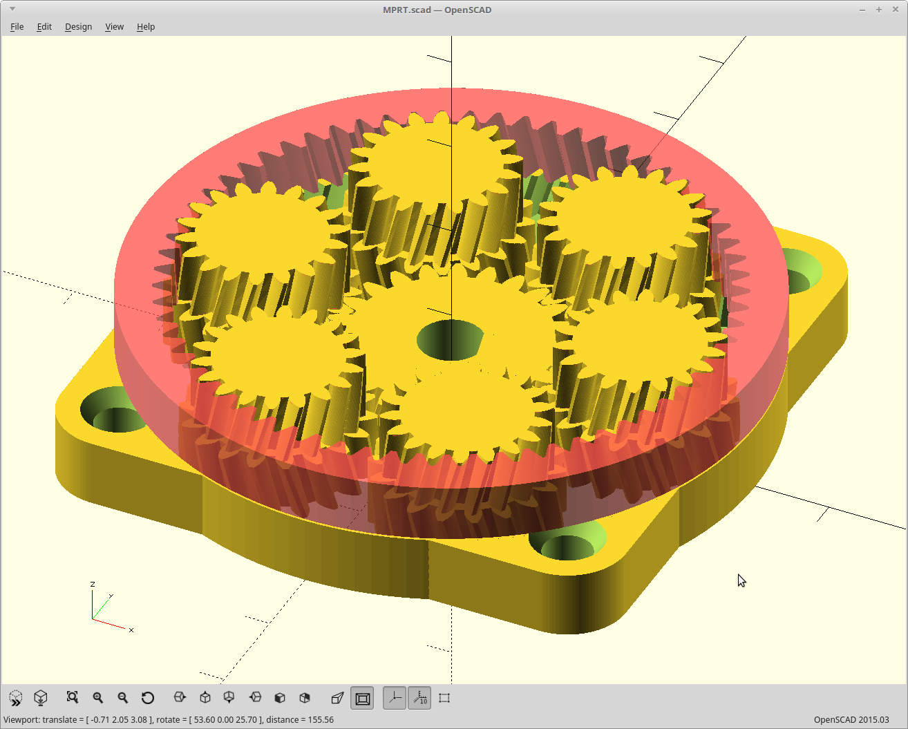
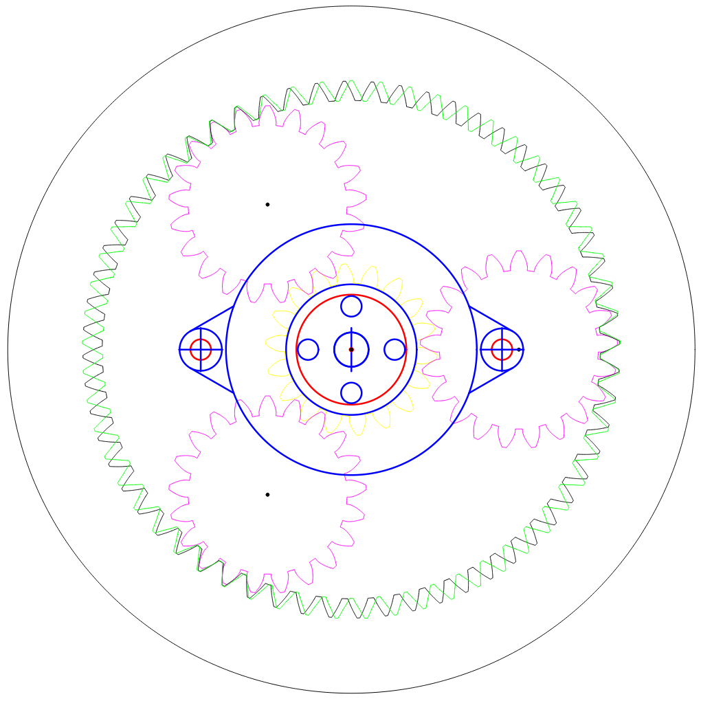
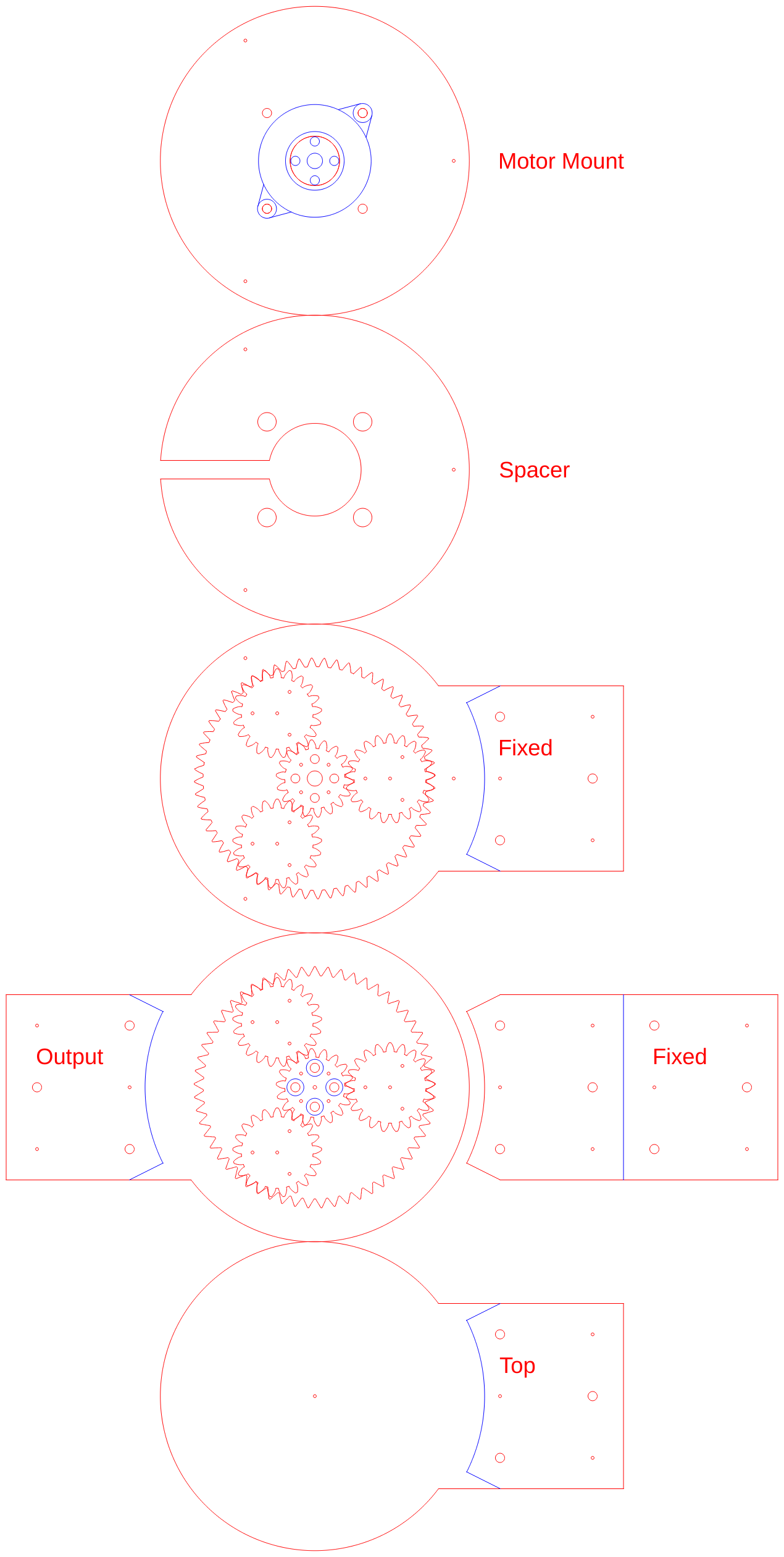
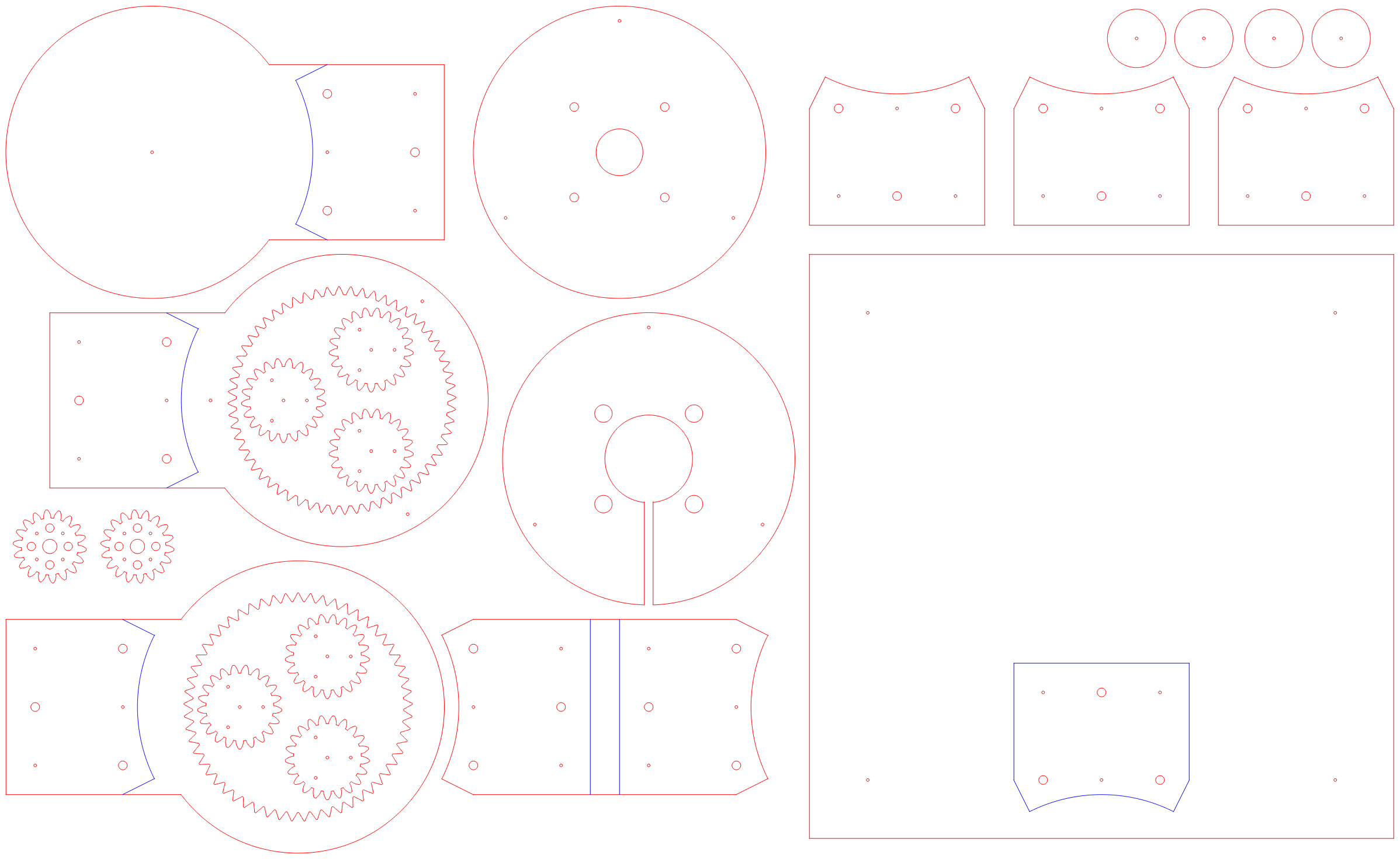
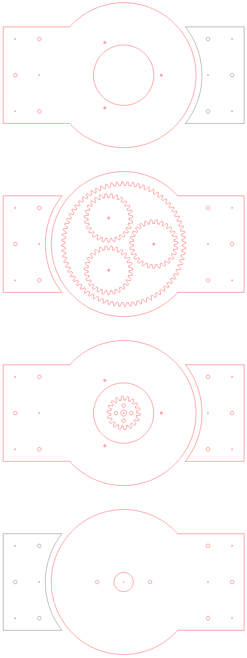
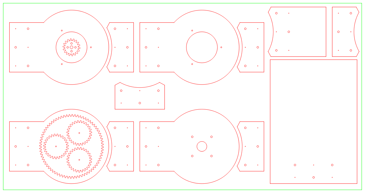
How this works
The power input turns the sun, and the sun drives the planets which rotate within a stationary ring gear. So far the same.
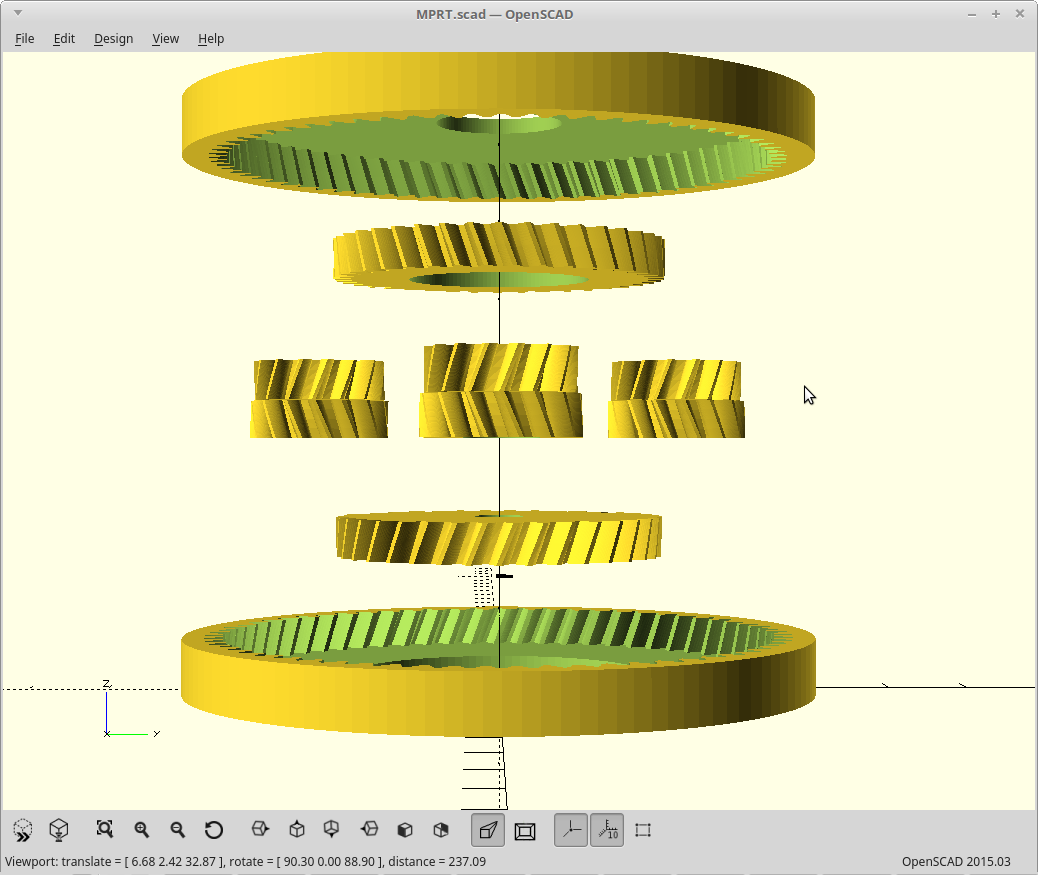
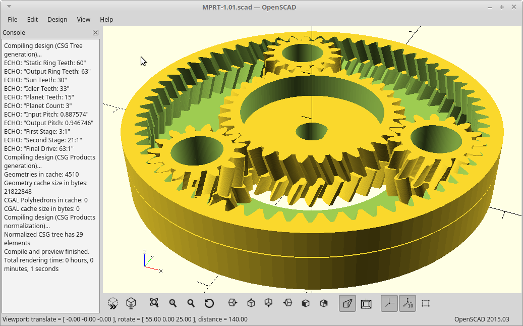
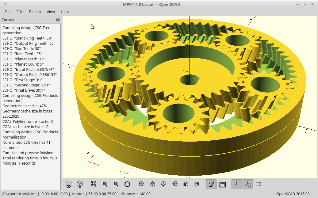
However, instead of taking your output from the planets, we allow the planets to just rotate within the ring, and cover them with a second ring gear. The second ring gear is constructed to vary from the stationary ring gear by exactly numplanets teeth.
Now, on each revolution of the planets the two ring gears will advance with respect to each other numplanets teeth. We take our output as the second ring gear and get massive gear reduction from it.
This arrangement gives you a gear reduction of:
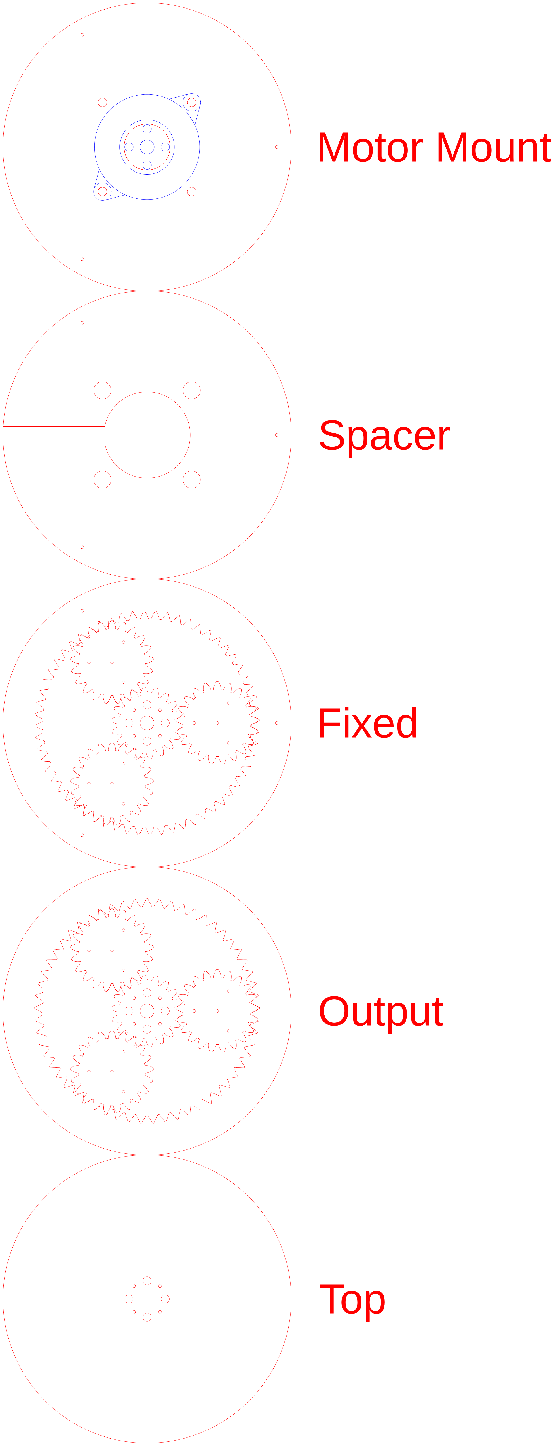
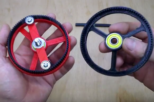
The result:
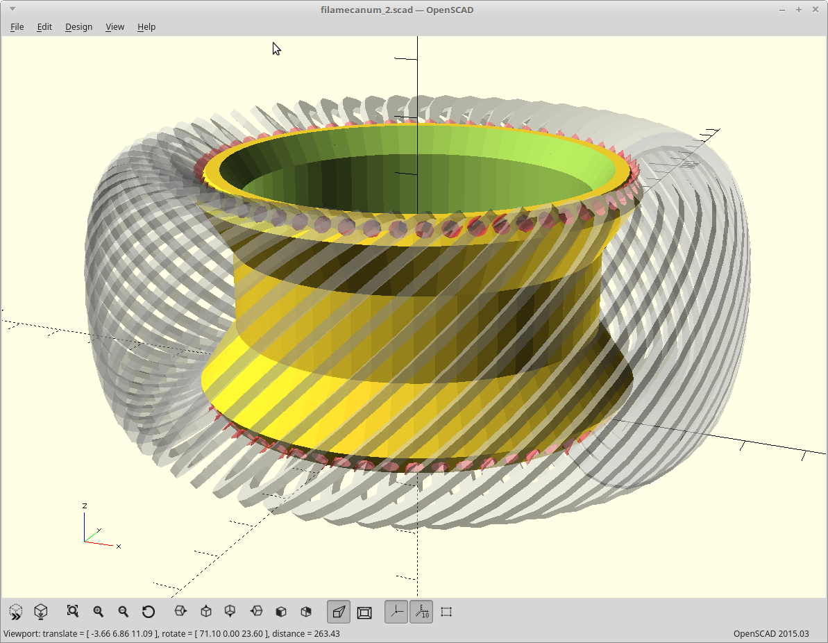
- We can now use a much larger sun gear to drive the planets, and still get significant reduction. Perhaps even wrap the perimeter of a BLDC outrunner.
- We only need one bearing, which essentially supports the joint itself.
- The vast majority of the force applied to the joint is right at the outer edge of both ring gears and drives both in opposite directions at multiple locations.
- We can get away with using much cheaper materials to do it.
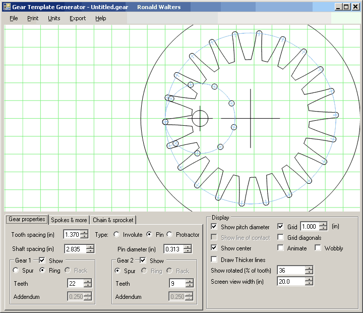
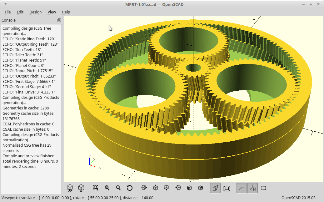
Picking a compatible gear ratio is critical, so here are the rules for the math required for the gearing. The simplified version for 3 planets is use a multiple of 6 for both the sun and ring gear teeth, and then an output ring gear tooth count of ringteeth - 3.
And here is a video.


 Simon Merrett
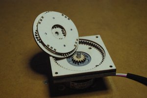
 Florian Festi
 Zoé
Zoé
Hi dekutree64, Yes cycloidal gears do not side. It seems to me that they would make a better base for my meshing code. A quick check on the Internet suggests a carrier will be necessary as the profile is sensitive to misalignment. Nice to discover a new path of exploration.
Regards AlanX