 Jan
JanDISCLAIMER:
After getting some attention because of this hackaday.com write-up I need to tell you the following:
This is a work in progress and NOT YET a safe and "turn-key" board which you could or should implement in your design blindly.
At the moment there's two versions.
- the working 1"x1" version which lacks the manual setting of the three parameters (they are set in software). The files of this one are here...
- the original version, which didn't work well because the regulator blew all the time
The original version is what I want to finish next, because it it the universal board which allows changing parameters "on the fly". It will have a fuse as well to keep the board from catching fire due to catastrophic events like short circuits...
Short summary
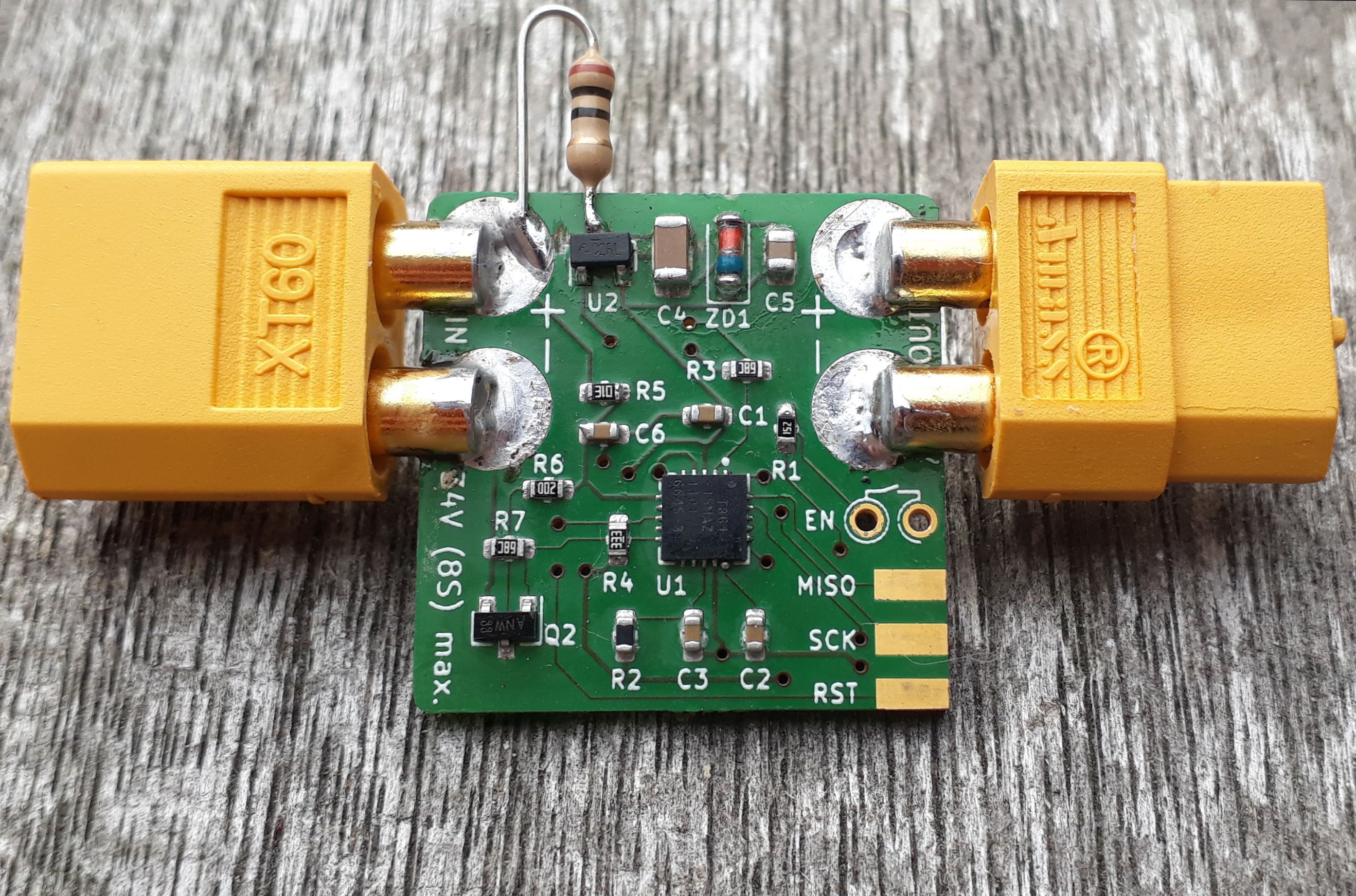
Use this board for all your battery powered projects, especially those using lithium ion or lithium polymer cells. It cuts the load from the battery if the user-set parameters are met and prevents the cells from deep-discharge, which can and will destroy the battery in the long run.
Key features
- Works from 2 to 8 cells.
- Battery-voltages vary depending on charge:
- 5.4 … 18.9V @ 2.7V/cell (max. allowed repeated discharge)
- 7.2 … 25.2V @ 3.6V/cell (nominal voltage)
- 8.4 … 33.6V @ 4.2V/cell (fully charged)
- Battery-voltages vary depending on charge:
- cuts off load when the battery voltage
- sags below a user set threshold
- for a user-set duration
- no automatic reset, user manually re-enables the device
- super low Rds_on N-Channel MOSFET for output switching
- supply current (ON, working): 2mA
- quiescent current (OFF): < 15µA
Basic mode of operation
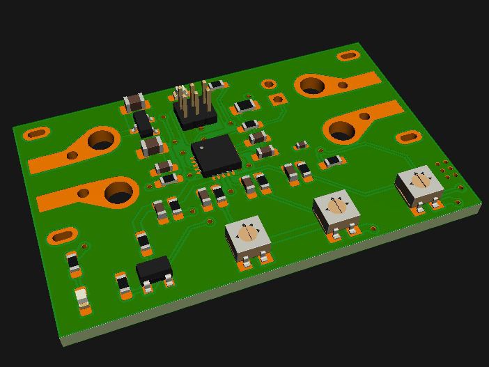
With three Potentiometers you set the cell-count, the cut-off voltage per cell and the time the voltage needs to be below the threshold to cut the load from the battery.
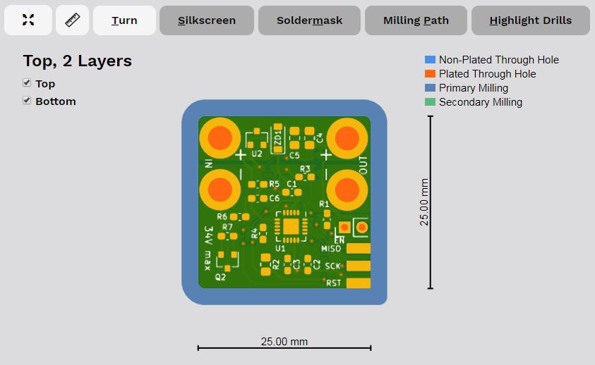
The battery is connected with an standard XT60 connector, which is common for Li-Ion and Li-Po batteries. The load is connected on the opposite side of the board with screw terminals. It is initially off.
The board is activated by a short press of a button and the load is switched on if the battery voltage is high enough.


 Daniel Grießhaber
 Torbjörn Lindholm
 The Big One
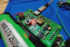
 Matthew James Bellafaire
ANy interest in helping me with a 125 v version?
DC
415.341.2281