Last time I reported that the 7 Inch Nextion display draws a lot of current that the Ultrasonics v1.1 board could not deliver. What you see is the display flash brightly then gets dark then boots, flashes brightly then dark in an endless repeating loop. It is constantly rebooting because it lacks enough power.
The original power source I used for 5V was the one on the power supply itself but that meant that parts of the board still gets power when I cut off the 24V switch to emergency stop the motors.
A double pole connector could have been used. One to cut the 5V and on to cut the 24V but I preferred a different approach.
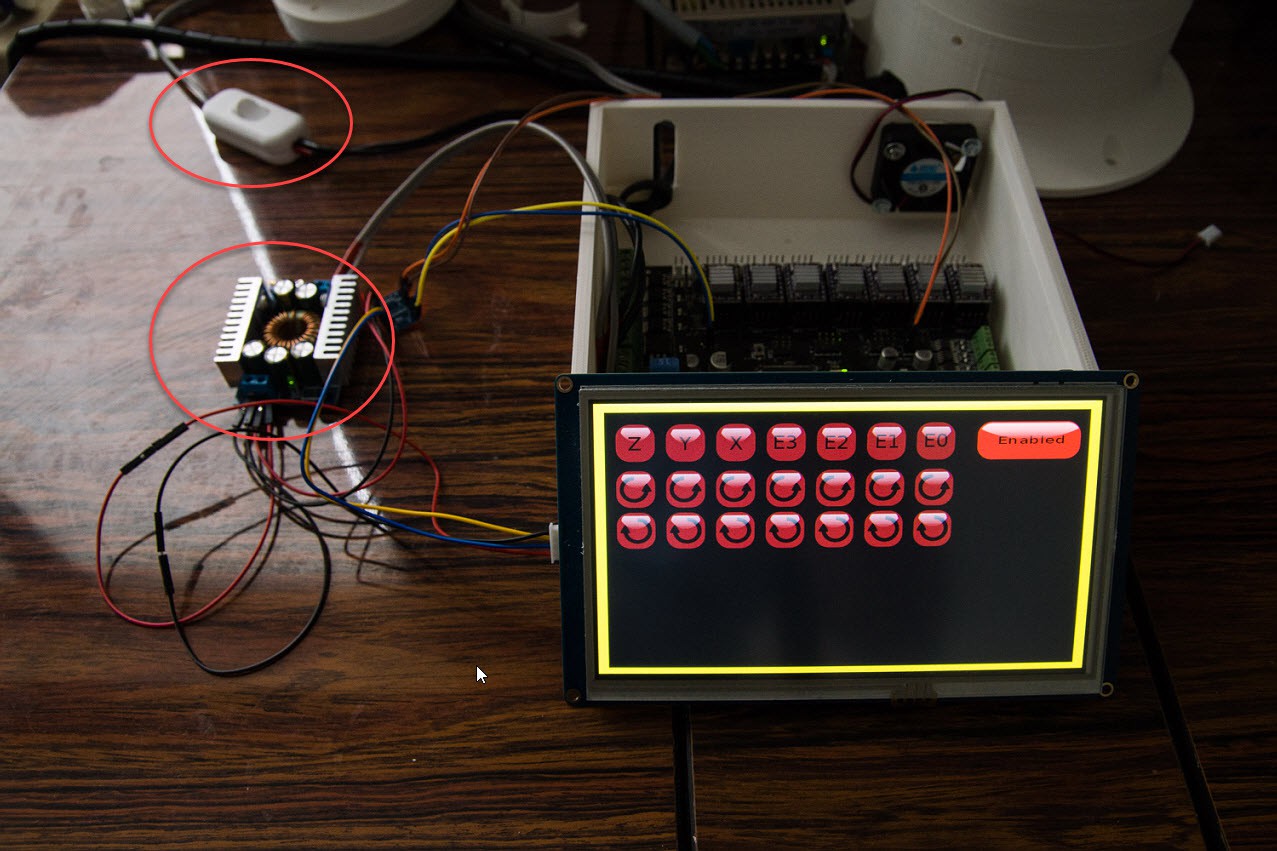
So I ended up with a buck converter that is now feeding from the 24V line and has enough power to deliver 5V for the Nextion display and future sensors or additional controllers. And can also act as a source to make 3.3V It reduces the number of wires outside the controller.
As you have noted this controller box is too small for the 7 Inch Nextion display.
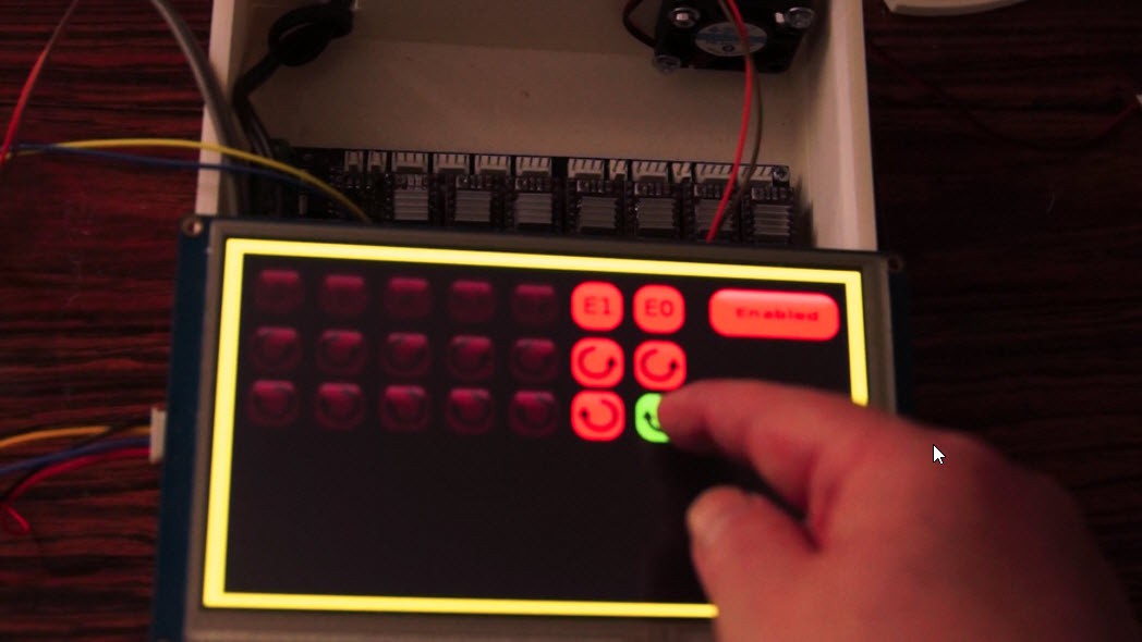
Here is an example how the screen is in action.
I used the order of the Polu drivers from left to right: Z, Y, X, E3, E2, E1 and E0
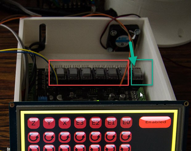 E0 is intended for the main base motor. This one draws the most current and heats up the most. The fan is directly blowing air on it. The idea is to also include the 24B to 5V buck converter into the box.
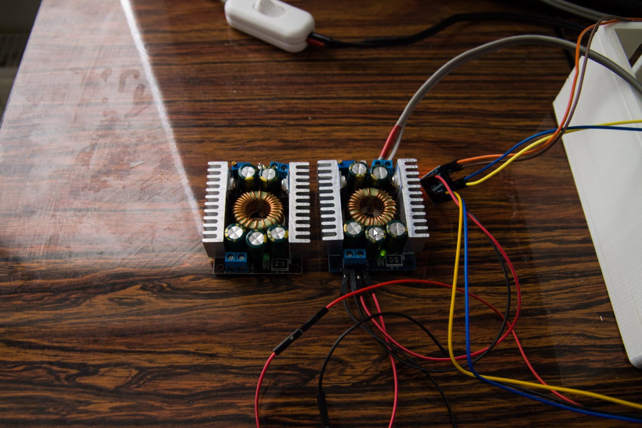 Because I ordered a 300W Buck converter it turns out bigger than expected. Tests showed that it stayed cool when I tested it on the Nextion display for an hour. So I decided to buy a 100W version that would be smaller.
And the big surprise came it looked exactly like the 300W version, identical components too. So I think that my 300W version is fake and can only support 100W..
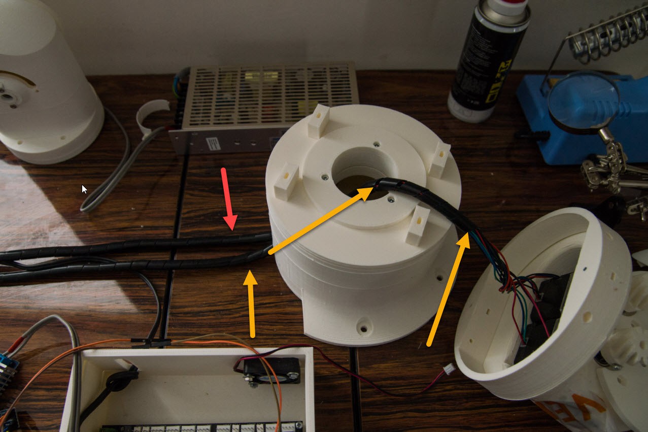
One last tip. Unlike Danny I am not going to go for a slip ring. I want to be challenged to adapt my software that it also has to take into account the limitations of the movement.
To prevent my cables to get caught into the cog mechanism I wrapped them up into a wrapper.
Originally I had all my cables into one cable wrapper, but when I had to demontage the parts I lost a lot of time to unwrap the cables in order to remove the top part. So I learned to use 2 different cable wrappings. One the goes to the base only, then one that goes to the upper part. And I maybe use one for the upper arm too.
Every stepper motor has 4 wires. This way I can find back what motor group is connected to what connector during the assembly and testing easily.
As I develop my software, I need a way to only test certain parts of the robots while the rest are disconnected. Disconnected means that they cannot do you any harm when I have a programming bug.
Discussions
Become a Hackaday.io Member
Create an account to leave a comment. Already have an account? Log In.
Not having a slip ring forces me to think out of the box and be more creative in solutions. It also forces me to think ahead and realize that when I develop code and want to debug it I actually may destroy my parts.
Are you sure? yes | no
Very nice log. Why didn’t you use a slip ring? It’s ideal to prevent your wires to become mangled.
It’s also very handy that I’am able to remove everything above Axis 1. In https://hackaday.io/project/26341-building-the-thor-robot-arm/log/65529-day-8-finishing-axis-1 I have added some pictures of the slipring. The slipring can rotate with 300 Rpm. http://www.ebay.com/itm/22mm-24-2A-24-Wires-2-amps-24-Conductors-Capsule-Compact-Slip-Ring-240VAC-300Rpm/391419579235
I might even change the 10 turn potentiometer to something else because I want Axis 1 to rotate freely so it can always take the shortest paths from point A to point B.
I even want to add a smal slip-ring In the next rotating joint. (Axis 4?). There is room inside the gear for it.
For the step down converter I order this one http://www.ebay.com/itm/DC-DC-5V-36V-to-3-3V-6V-9V-12V-24V-5A-Buck-Step-down-Converter-Voltage-Regulator/262320245865. It is a little bit smaller. I want to mount one in the PCB above the bearing ring.
Wouldn’t it be nicer to use a braided sleeve instead of the wrapper to bundle your cables. For example: http://www.ebay.com/itm/5-meters-of-Shakmods-Expanding-Matte-Braided-Sleeving-Cable-Harness-11-Colours/161766868973
Are you sure? yes | no