Close
0%
0%

DLT one - A Damn Linux Tablet!

Modular Open Source Hardware Tablet that is easy to hack and can run a standard Desktop Linux Distribution (or Android)

Public Chat
Similar projects worth following
Proper Linux Tablets unfortunately just dont exist and certainly not ones that are also open hardware.
I want hardware that does not lock me into a specific OS or cripples other options by the lack of drivers. I'm also sick of the lack of modularity and repairability of modern hardware.
So I will create the following.

A basic system for a modern and highly performant portable device (e.g. Tablet) in the 7-10" form factor.

The electrical and mechanical design will allow for a multitude of form factors in the future, basing on a shared approach on how to interconnect hardware, so reuse between form factors will be possible.

These newly developed standards for modular portable devices will be open to everyone and the same goes for the design of the Tablet that is being developed here.

For more details please read my project logs and the detailed description below.
The development started with the HaD Prize 2019 and you will be able to follow every step of it.

Current mobile hardware is closed and monolithic. Repairs are hard and modifications or upgrades impossible.

This is unsustainable, keeps small companies out of the market and stops users from adapting devices to their own needs. I want this to change!

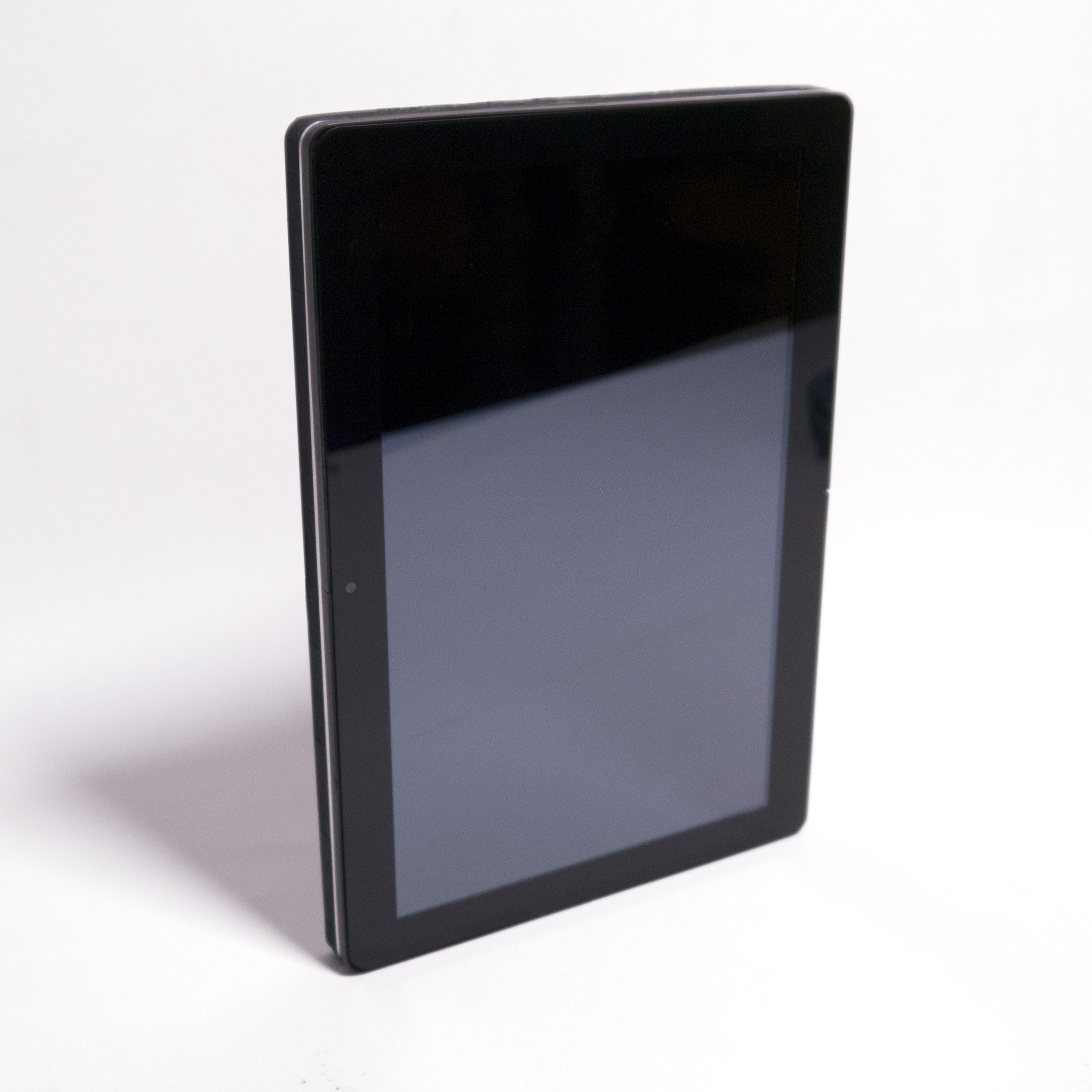
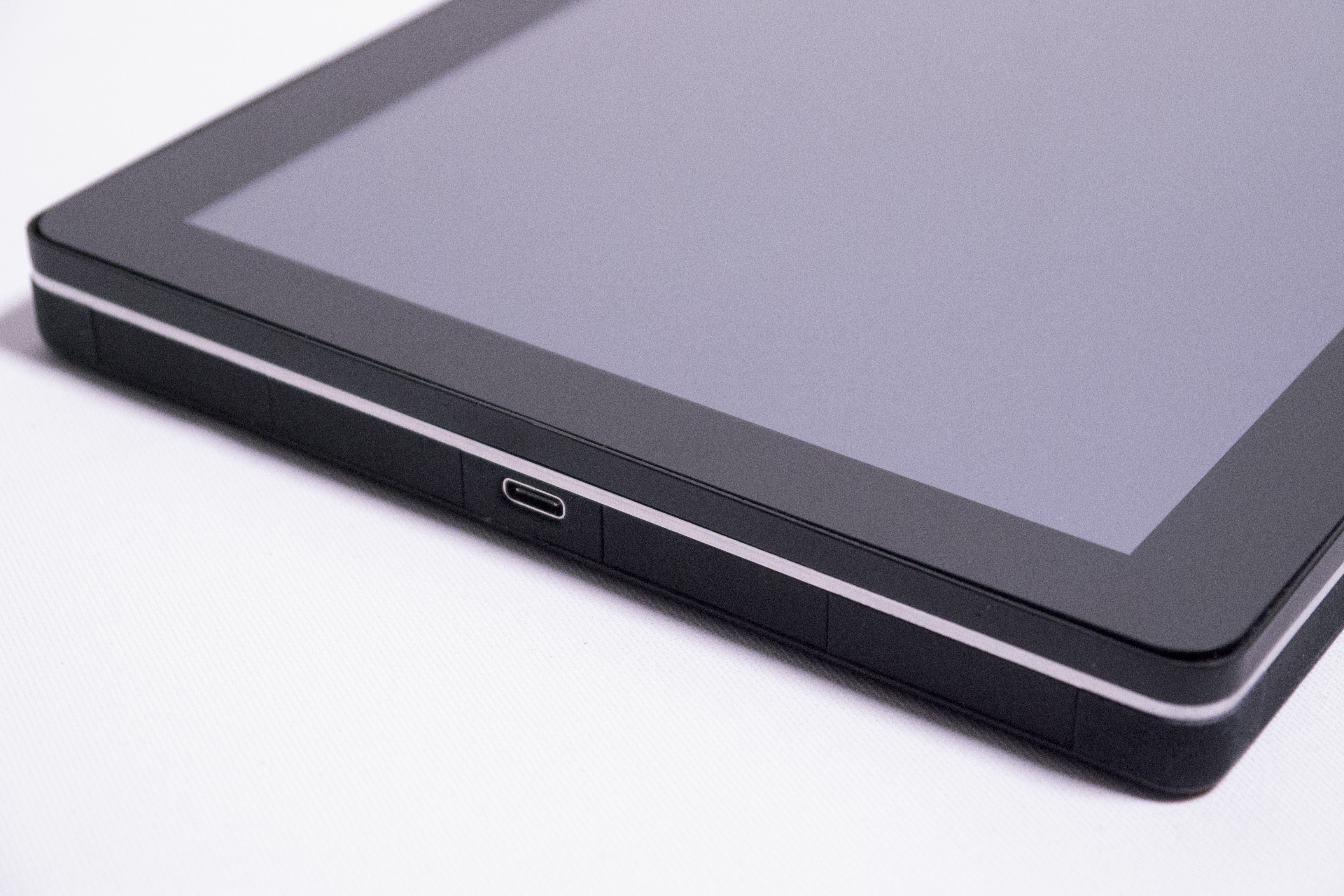
To do that I am creating a highly modular, upgradable and modifiable tablet with a clear standard for open mobile computing. This lets companies and enthusiasts change what they need and reuse the rest.

The highly modular, upgradable and modifiable design lets them spend more time and energy on the bits they care about (some niche sensor or a CAN bus perhaps) without being bogged down with the bits they simply need (a screen interface or battery management).

The clear and open standard provides a framework for community development to feed back into the ecosystem in a future compatible way.
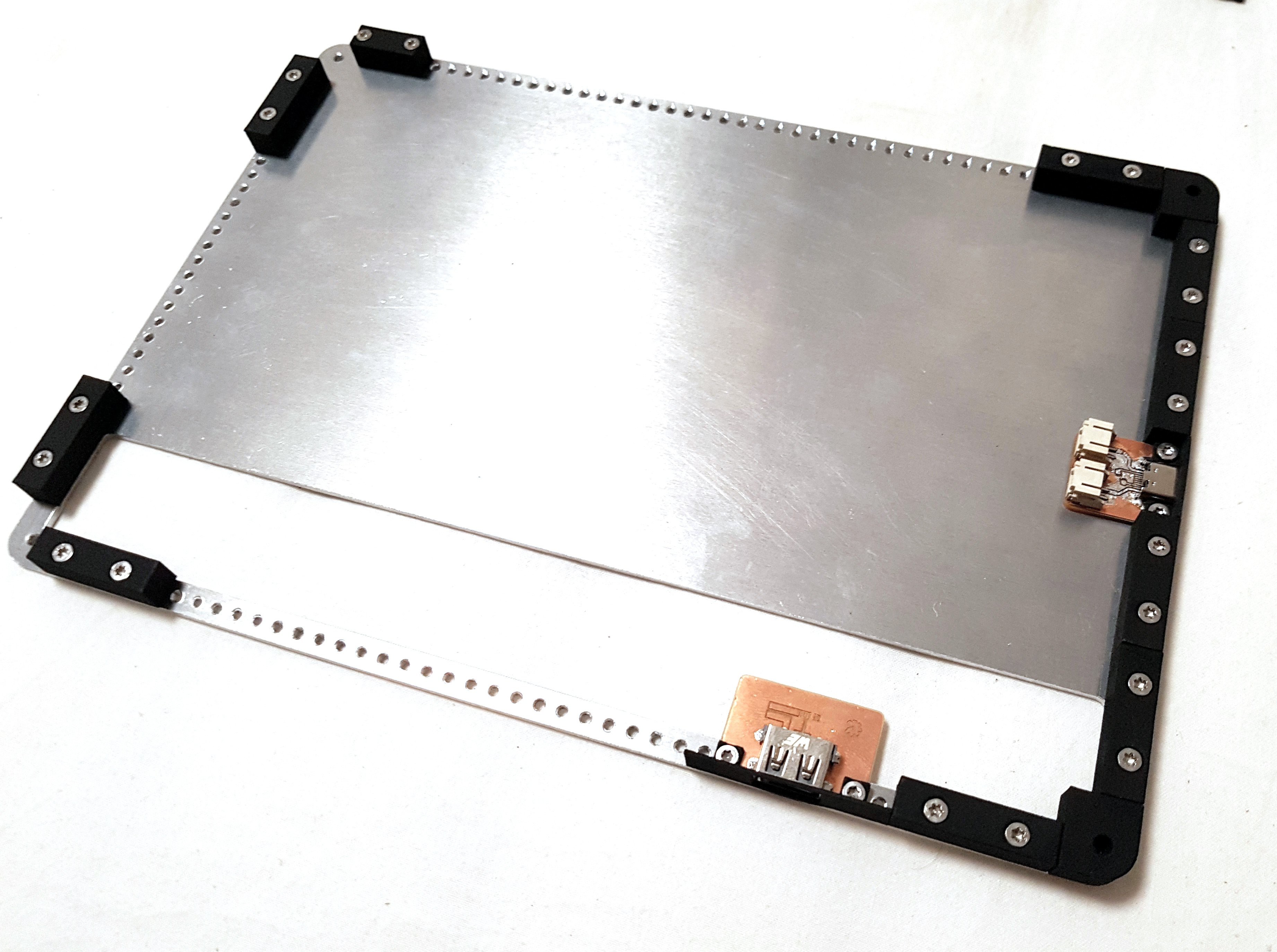
This will be achieved by defining a mechanical standard for creating cases and an electrical standard that defines interconnects, pinouts and behaviour.

This should enable the re-use of peripherals through different motherboards, housing different SoC's, from all kinds of performance spectrums, keeping the cost of replacement and repair down to a minimum and enabling very quick development of new features/peripherals for the ecosystem.

If you'd like to drill down into the details, here are the most important logs.
If you have time though I recommend just reading the complete logs in order :)

https://hackaday.io/project/164845/log/166748-mounting-plate-mock-up

https://hackaday.io/project/164845-dlt-one-a-damn-linux-tablet/log/169428-modules

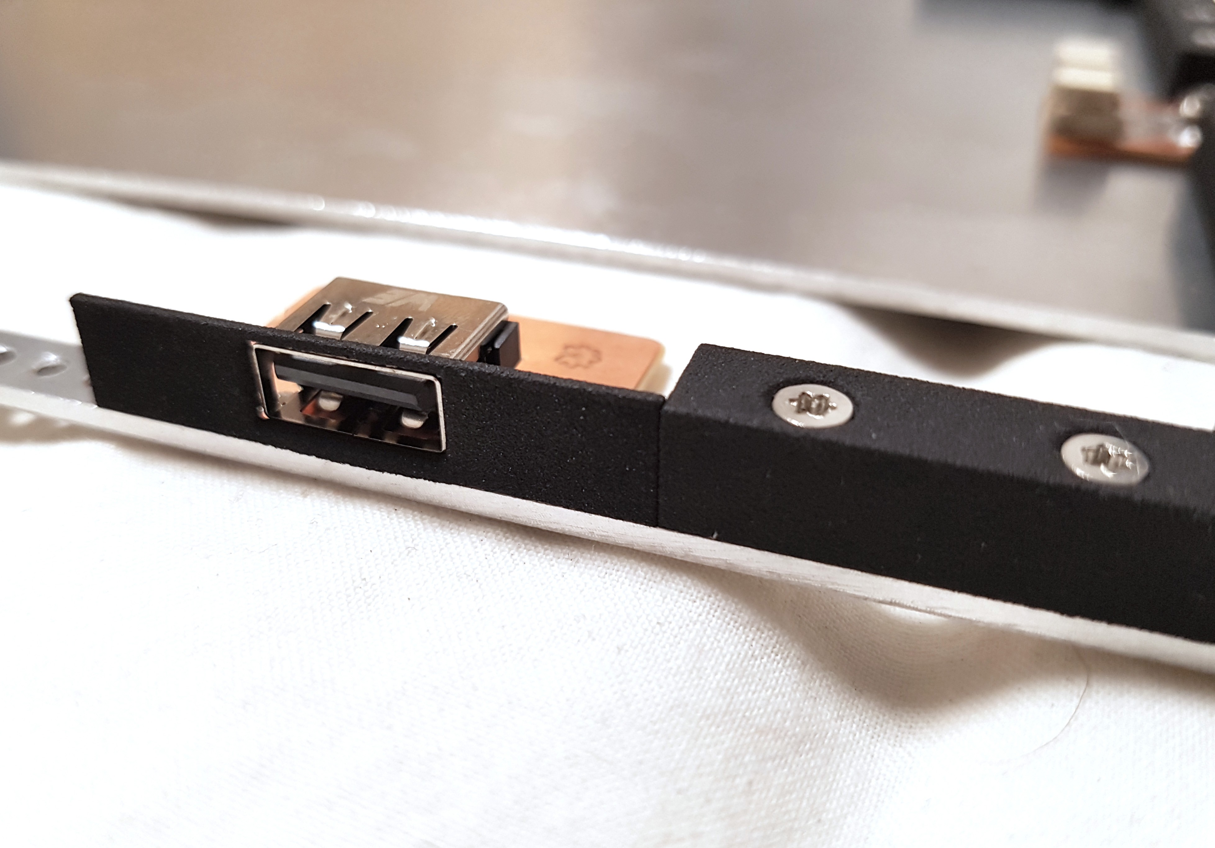
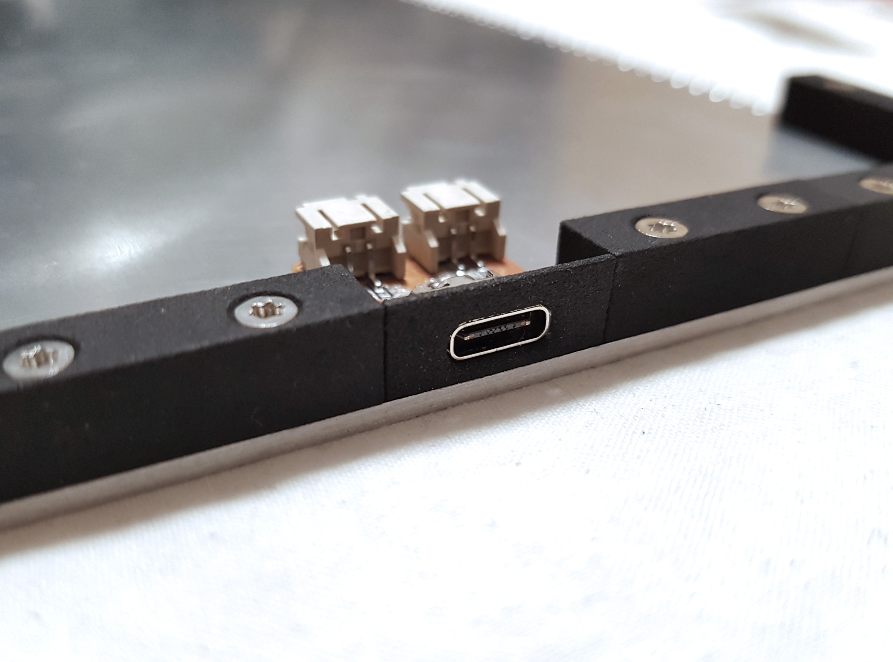
https://hackaday.io/project/164845/log/167049-peripheral-bezels

https://hackaday.io/project/164845/log/165497-manufacturing-and-the-target-audience

https://hackaday.io/project/164845/log/163897-mechanical-design

https://hackaday.io/project/164845-dlt-one-a-damn-linux-tablet/log/169433-pricing-and-high-level-bom

https://hackaday.io/project/164845-dlt-one-a-damn-linux-tablet/log/169307-prototype-assembled-albeit-some-challenges

Note:

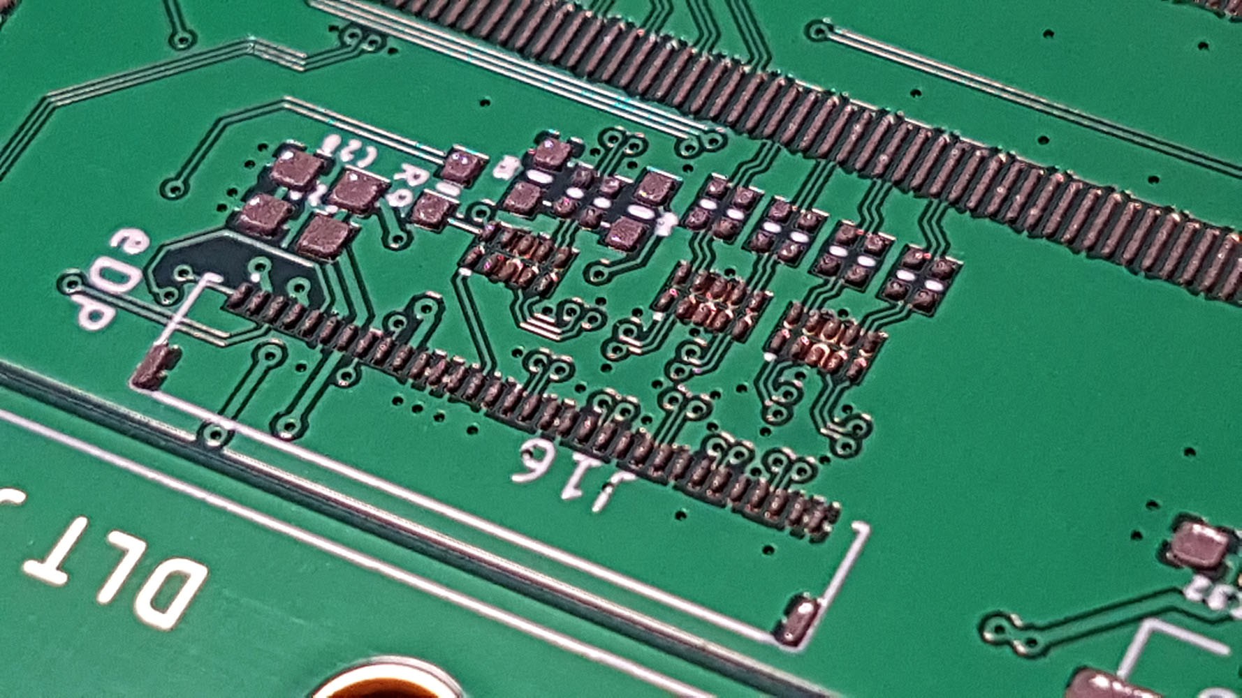
The standard is in concurrent development but wont see a release until the Tablet hardware itself reached a mature status because that's when the Standard will also be mature enough to be released. All the learnings from the development are important for the development of the standards, its not something I can just define beforehand or else it will be too narrow minded. I will share specific details on the standard before that of course to get input from others in the community but I will not release a white paper until things have settled. I had it happen too many times that people jump on the bandwagon during development and develop with incomplete information which becomes deprecated later on, I want to avoid that. If your are interested either way, have a look at the prototype design files which I update as they are being made but be aware that this changes rapidly. If you want to help with the design, get in touch!

Motivation:

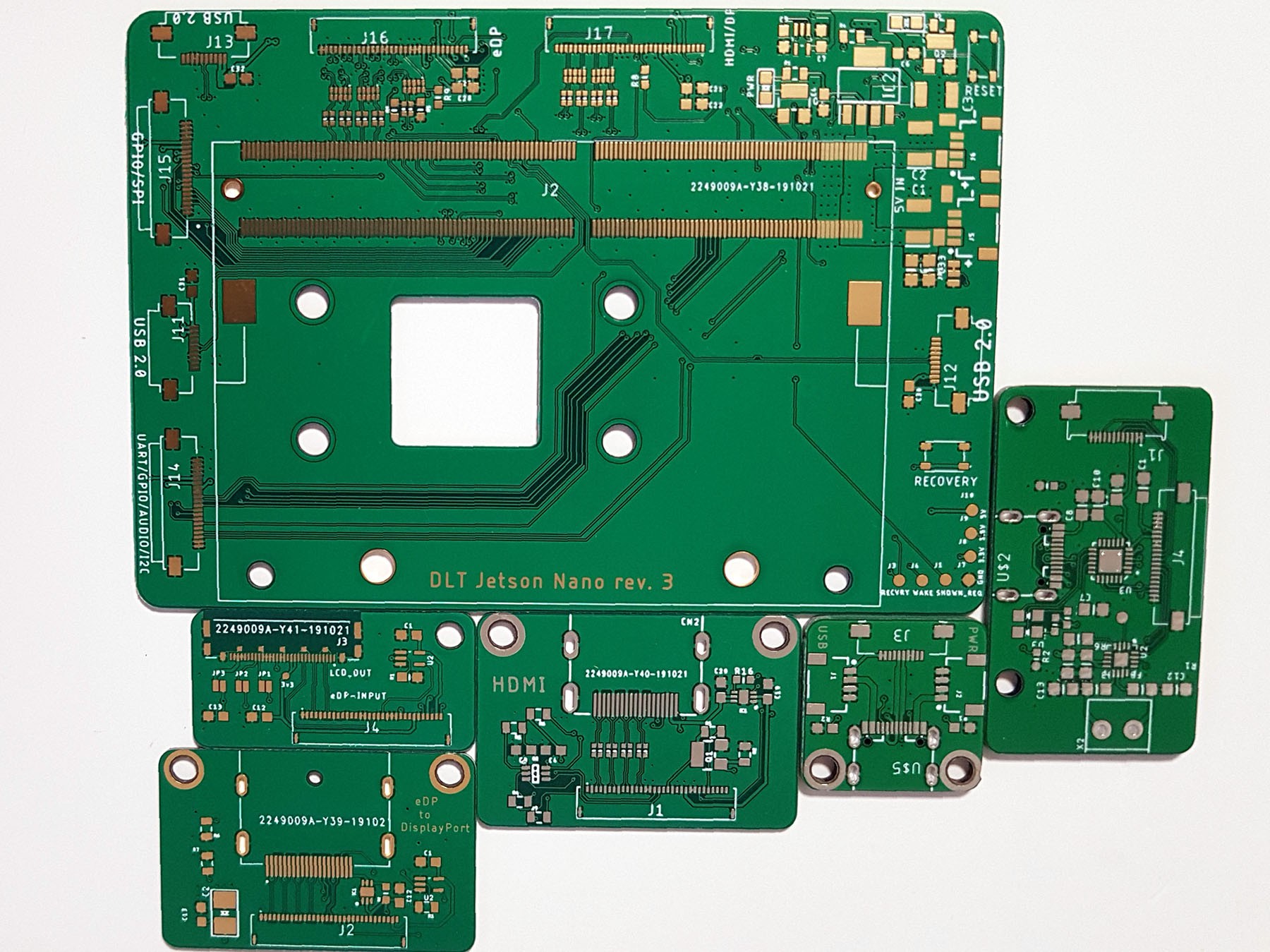
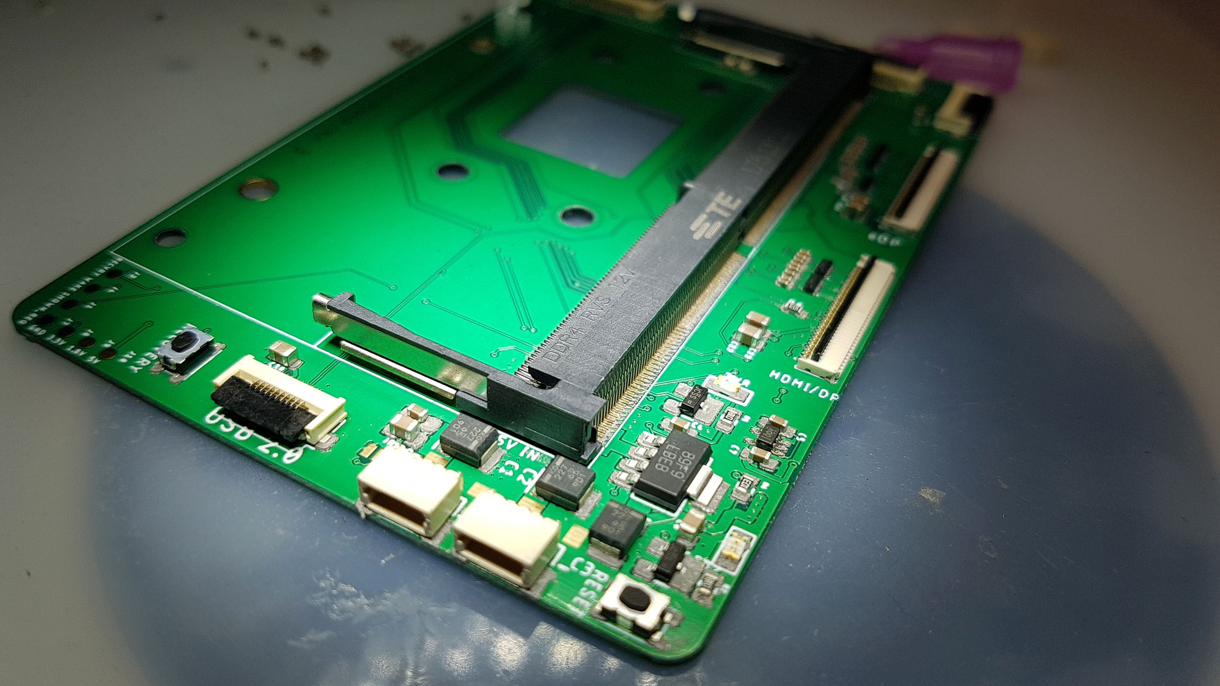
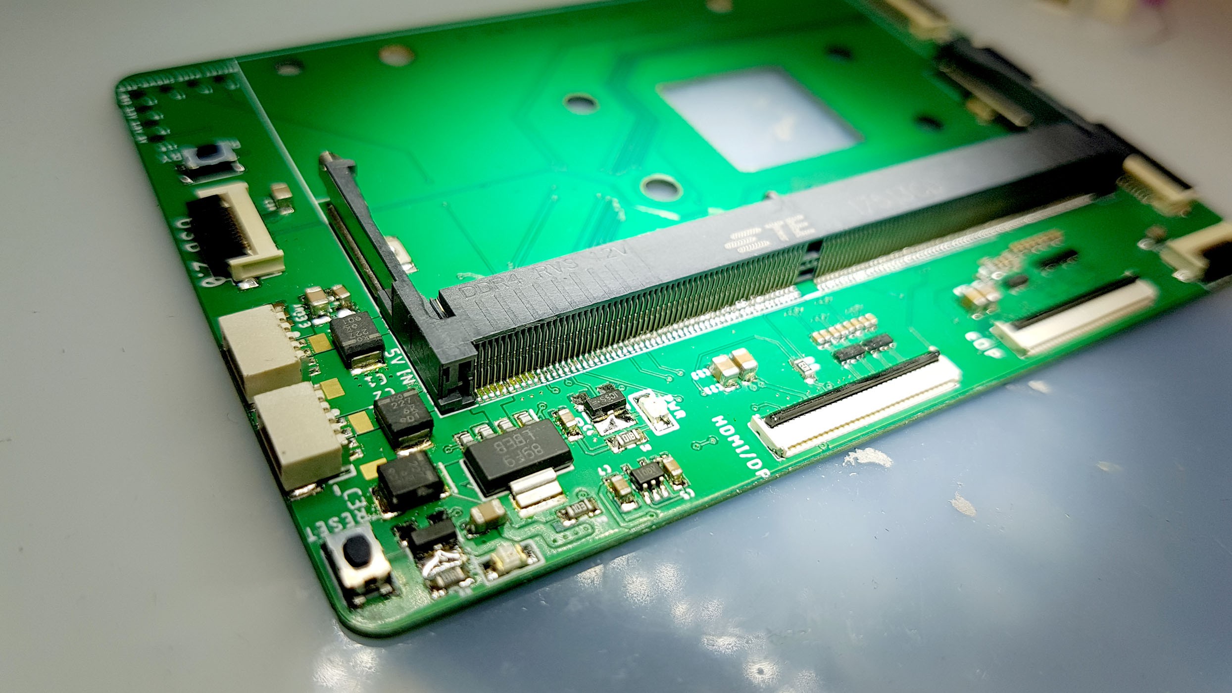
For years I've been wanting to create a tablet like device based on a SoM (System on Module). Doing something from scratch, routing DDR3 RAM, eMMC etc. didn't seem realistic to me, this is not only really hard but also very expensive. So SoM it is, which comes with the additional benefit of user up-gradability if the SoM manufacturer stays true to their pinout with successor products, which they usually always do, at least for a few generations, which usually means you get compatible hardware for 10 years or more.

Back then I started out with the Raspberry Pi compute module but the more I thought about my specs the clearer it was to me that it just wont cut it.
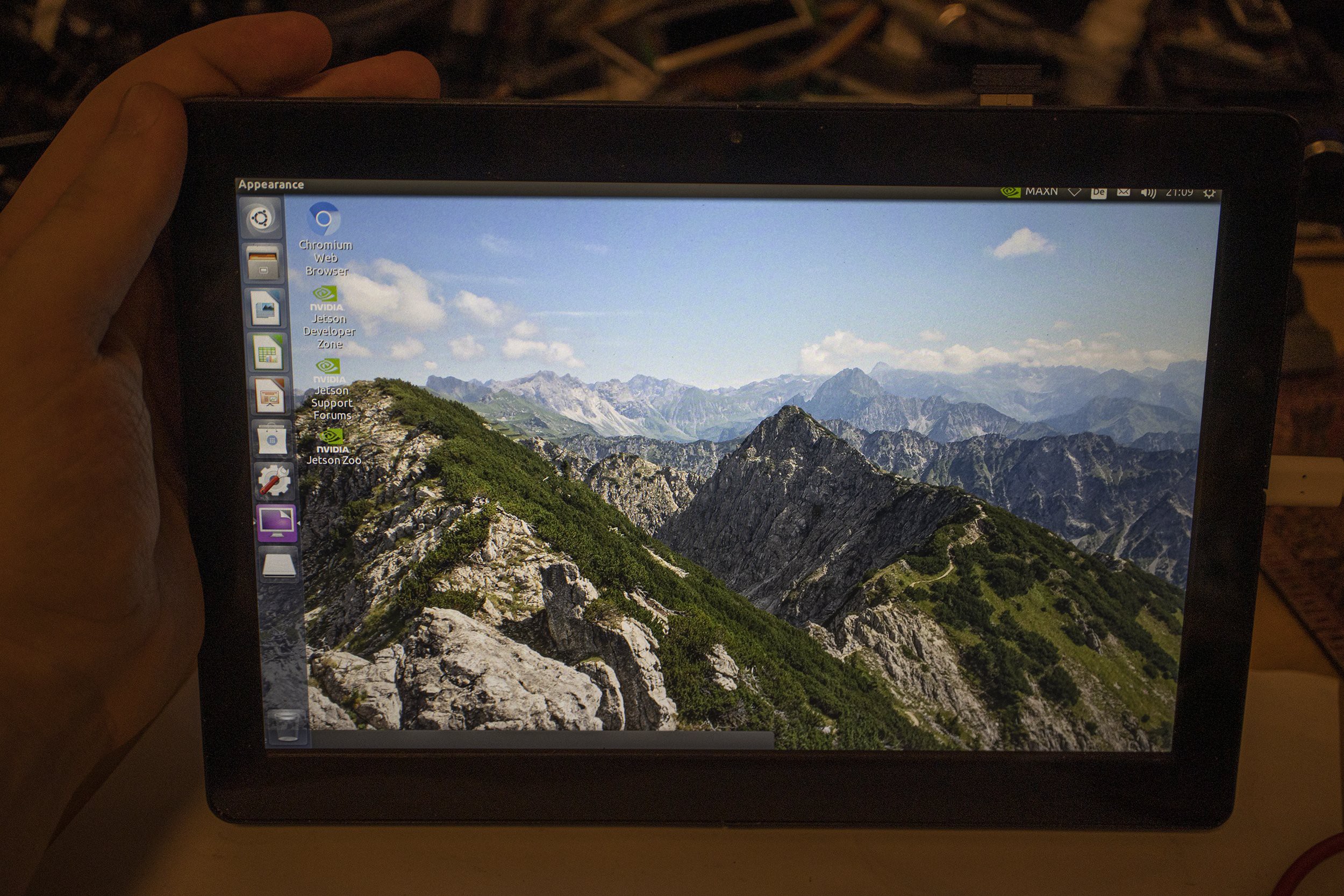
I wanted something that can run modern applications, something that is actually very usable and is not just a cool thing on paper.

The past years I've been looking around for affordable SoMs that offer enough performance to be viable, until now there were either cheap outdated SoMs or ones that mainly target...

Read more »

Git Export 30.09.19 - A Damn Linux Tablet.zip

Git Export of the linked github repo. Please use the github repo if possible. Includes PCB Design Files, CAD Files, BOM etc.

x-zip-compressed - 6.33 MB - 10/01/2019 at 11:13

Download

  • Next steps

    timonsku08/24/2020 at 19:31 2 comments

    Personal life is keeping me quite busy at the moment and other projects are smiling at me but there has nothing changed towards getting this to a finished point eventually.
    I have assembled the old case parts with the now working display just to give things a test while the mainboard is actually sitting inside the case together with the display. Right now it is of course USB powered as I have not tackled the Battery Management System (BMS) yet.
    Though the BMS is quite far up on the todo list and I got some great partners from the community that are helping me with this complicated part of the tablet.

    But lets look at some pretty pictures first before I go into more details on the next steps. Please keep in mind that these are the same super rushed prototype case parts with all their blemishes and mistakes from my Hackaday Prize submission 1 year ago. It flew half way around the world and back :)

    The screen really is quite beautiful with its 2560x1600 10".


    While assembling the pieces I quickly noticed some things that I want to change. Its fascinating how quickly these things come to you when you had some distance to a project for a while.

    First thing is the plastic bezel in which the screen is glued into. I will merge this with the aluminium plate and make it one milled piece. There is little reason to not have these two things as one. Both are fully dependant on the display being used and can't be further modularized.
    This should give a better rigidity of the display assembly too and it also allows for the actual mounting plate part to be thinner, shaving of another 1-2mm of the total thickness which is quite substantial.

    Thickness in general is still a point I want to improve on. On one part it is very much dependant on which connectors I want to support, on the other it depends on how thin I can get stuff without making things unstable.
    If I were to not make it modular I could easily get it down to ~10mm but I'm not making "iPad but Linux" here. This is not the project for that and it will never be.
    I want to push what we can do in the mobile world with a modular concept without going crazy like Google did with their Project Ara approach.

    Making something that can also serve as a robust base for a plethora of other products is a goal here, so keeping things modular is still the number one reason to do this project.

    Next up would be a rework of all the case parts. The current prototype served its purpose of testing my assumption and developing the concept further.

    Next up is also the BMS as mentioned earlier, this is a very crucial part and comes with its own problems. Once that works it is pretty close to the bare minimum of what you could call a tablet.
    With the mainboard, screen, case and BMS the most complicated pieces are solved. Things like sound, buttons, WiFi etc. all have their complexities but aren't things very specific to this project and is something I can ask for help more easily as this is something people can work on with just a Jetson Nano devkit. These parts will also need a whole lot more software work to get them working right. A lot more Linux Device Tree work ahead on that front.

    It might be a while again until I can do another sprint but it is most certainly coming :)

  • Display is finally working

    timonsku07/05/2020 at 15:11 5 comments

    First of all sorry for the huge absence of updates. I've been updating my small steps mostly via twitter, then took a longer break from the project from Feb to May as I've been a bit burned out.

    So what happened since the last update? I tested the new revision, unfortunately no change, the issues still persisted. While the pinout was corrected the Display was still staying black, I was successfully communicating over the AUX channel again but it was failing at the link training stage.

    Then followed a long stage of debugging, diving deep into the Linux Device Tree setup of the Jetson Nano. Which was very educational for me but unfortunately did not bring me closer to get the Display working. I was suspecting that the default device tree was assuming some bit rate settings that are suitable for desktop monitors but not actually accepting the request from the display for a lower bitrate mode. Eventually I got it to advertise the lower bitrate but this did not change anything.

    After that I was a bit burned out and had really no good idea why it wasn't working so I took a bit of a break, then COVID happened and my general motivation to do electronics plummeted.

    I got back to it a few weeks ago and did another sprint to get it working.

    The first thing I wanted to try was to make an adapter that would allow me to connect my desktop GPU to one of the panels to see if I experience the same issue there.
    I milled this on my Bantam Mill. Turns out standard DisplayPort cables don't carry the 3.3v line so I had to bodge an LDO on there.

    With this setup I had the same issue with my desktop GPU.
    One hunch that remained was that it might have to do with the fact that the displays I was trying to get working were all 2 lane displays. DisplayPort defines that for embedded devices it is ok to use only 1 or 2 lanes instead of the full 4 data lanes to save cost and complexity for less high resolution displays.

    This turned out to be indeed the culprit. I found that one display sample that I hadn't really touched before because I assumed I accidentally ordered an LVDS panel turned out to be 4 lane eDP panel. So I milled an adapter for that going from my pinout to the displays 40 pin pinout to test my theory that the Jetson is not able to adapt to displays with less than 4 data lanes.

    And guess what. It worked! FFS.
    I also quickly found a hint for the culprit in the driver, while display is requesting that the amount of lanes be lowered, the driver never actually does. This happens a few times until the driver determines there are no more lower lane counts to check albeit it never actually doing that. The driver defines a struct with the the three different lane counts to check but it seems it never actually uses it other than to check for how many times it has to lower the lane count.
    static int lane_fallback_table[] = {1, 2, 4};
    So it keeps on iterating over this struct but because it never actually does anything to satisfy the displays request, it eventually gives up after spamming the kernel log with vague and unrelated error messages that had sent me down the wrong rabbit hole. Until quitting with saying that it tried all lane count options (which is a lie as we now know).

    [    6.272838] dp lt: new config: lane 0: vs level: 2, pe level: 1, pc2 level: 0
    [    6.279969] dp lt: new config: lane 1: vs level: 1, pe level: 0, pc2 level: 0
    [    6.287099] dp lt: new config: lane 2: vs level: 0, pe level: 0, pc2 level: 0
    [    6.294227] dp lt: new config: lane 3: vs level: 0, pe level: 0, pc2 level: 0
    [    6.301362] dp lt: config: lane 0: vs level: 2, pe level: 1, pc2 level: 0
    [    6.308150] dp lt: config: lane 1: vs level: 1, pe level: 0, pc2 level: 0
    [    6.314936] dp lt: config: lane 2: vs level: 0, pe level: 0, pc2 level: 0
    [    6.321724] dp lt: config: lane 3: vs level: 0, pe level: 0, pc2 level: 0
    [    6.328508] dp lt: tx_pu: 0x60
    [    6.332014] dp lt: CE retry
    [    6.334810] dp lt: switching from state 3 (channel equalization) to state 3 (channel equalization)
    [ 6.343761]...
    Read more »

  • Rev. 3 and the Hackaday Prize

    timonsku12/17/2019 at 15:54 1 comment

    I've been slacking. I wanted to write this entry weeks ago but issues with the latest revision have somehow kept me from writing about it.

    It's a been a crazy 1.5 months. You may have already heard it but the project on the 2019 Hackaday Prize for Best Design :)
    Which was totally awesome, I was at Supercon and showed of my prototype and received the award in person. It was a great experience and it was lovely to talk to so many of you. The enthusiasm around the project is just tremendous.


    Now about the latest PCB revision. As I already mentioned it involved a lot of design changes. The biggest being that I switched to the production module of the Jetson Nano SOM and that I switched to a reverse mount SO-DIMM connector.
    The PCBs are gorgeous, I use JLCPCBs impedance controlled JLC2313 stackup which allows for really tight diff. pairs.
    It was a really large order as I revised not only the motherboard but also all the peripherals I made so far.
    A big thank you to JLCPCB for their continuing to sponsor this project, while they are crazy affordable, all these 4 layer ENIG boards and stencils amount to quite a bit of money over time and having a PCB sponsor here definitely helped the pace of the project a lot.
    Here some pictures of the PCB and pre and post reflow. Reflow was really good this time, only 2-3 minor shorts.


    Unfortunately this special stackup is only available in green. Understandable given the few orders they probably get for these.
    Apart from a reversed tantalum cap (which you can see in the last pic) and a missing pullup for the (now slightly smarter) 3.3V LDO it booted up just fine but to my great disappointment, none of the display outputs worked, yet again. Too an even larger dismay, none of the USB ports worked either and I had no clue why. The pinout of the new connector seemed right, it was booting and I could connect to the debug UART of the Jetson.
    So I started to suspect a device tree issue originating from the change from the pre-production to the production Jetson Nano SOM.
    I had a many weeks long back and forth with the Nvidia support to find the culprit. I learned a lot about Linux device tree and the specifics of the Jetson in this regard to flash changes in the device tree to the SOM. Which was time well spent but this weekend it turned out that this wasn't the root cause at all.
    The footprint of the reverse mount SO-DIMM connector was wrong! You might think that this was the first thing I checked, which I did. All seemed well everytime I checked it but my culprit was the way I was checking the footprint. I verified that Pin 1 and 2 and 259 and 260 were in the correct spot and I verified that the power pins line up the way they are supposed to, same with the UART, which they did (otherwise I would have gotten some smoke too).
    So what on earth was wrong? Turns out that the provider of the footprint, SamacSys had switched the pin numbering half way through! After the key notch they flipped it and changed back again when arriving at pin 1 and 2.
    So right to Pin 2 was no Pin 4 but instead Pin 3! So everything was upside down and all the ports I was testing, USB, DP, HDMI were all on this faulty part of the footprint!

    Just to be clear, both footprint and schematic are correct but the pin assignment was wrong half way through!


    So back to the drawing board, I fixed the footprint (SamacSys was also very quick to reply and get on the issue btw. except for this instance their footprints were perfect so far, 90% of the footprints on this board are from them). I rerouted the broken parts and ordered revision 4, lets hope that now, finally everything will be all right!

  • Rev. 3 designed and on the way

    timonsku10/29/2019 at 21:54 0 comments

    I've finished designing rev. 3 of the motherboard and its actually arriving tomorrow :)

    I may have figured out what the issue with eDP was. I noticed that lane 0 and 1 were running on the bottom layer and the reference plane which I believed to be GND was actually 5V. While you can switch reference planes you have to give the return current a path to follow along by placing capacitors at the spot where you cross over, which of course I didn't do and the impedance probably sky rocketed.

    I fixed this now and everything is referenced to GND at any point. Lets hope it works again.

    I also went with the reversed connector so the module is inserted upside down with the SoC facing towards the PCB. I added cut-outs to the PCB so I can place a piece of aluminium or copper in the cut-out and pipe the heat from the SoC directly into the mounting plate which will act as a gigantic heat sink. This safes tons of height and hopefully solves the lurking issue of thermal dissipation.

    Other than that no crazy changes. I switched from JST PH to JST SH which is more low profile. It also meant switching to 4 conductors but that is actually a nice thing because thats also the type of cable Adafruit and Sparkfun use for their qwiik/stemma qt products so getting cables for that is really easy. I thought ahead and put the polarization in a way that wouldn't end in dead ICs if someone should ever have the idea to plug their qwiik boards into those power ports...

    I also added a different 3.3V LDO which gives me a power good signal that I can use to power up certain things only when they should be. This is a thing when being connected to external circuits like a PC monitor, don't want those to back power you when you're shut down. So the 3.3V power good signal controls a load switch for the VCC connection of those peripherals.
    This is part of a more robust layout that I will continue to add with further revisions, I skipped on that so far as it adds overhead that is not really needed in a controlled environment during prototyping.


    I spare myself posting renderings as the real deal is arriving soon, so I will update again when those arrive.

  • Pricing and High Level BOM

    timonsku09/30/2019 at 23:27 4 comments

    I haven't really shared any pricing details yet. For good reason of course, a lot of that really depends on quantity but I wanted to give you a ballpark of what is to be expected.

    So lets break it down, starting with the heart of the tablet, the SoM.

    This is the most flexible part of the pricing because you can get wide variety of SoMs. The one I'm currently focusing on for the first motherboard is the Nvidia Jetson Nano which has a somewhat odd pricing. If you buy yourself the devkit you get the SoM for 99$ or about 90€. If you buy the production module you are looking at 130-150$/120-138€. The cheapest price being qty. 1k.

    So if we were to start out with kits instead of assembled Tablets it would be a lot better value to have customers buy themself a devkit and steal the module from there. Given that Nvidia updates the dev kits, the production modules are actually not pin compatible, the current dev kit is using an older beta pin out, I have a third party devkit in the post atm to work with the new production module for rev.3 of the motherboard.

    Looking at other SoMs we can also get low budget i.MX8 SoMs with dual core CPUs and 2GB RAM for around 80$/73€ in QTY 10. They get considerably cheaper when buying in larger volume of 1k or 10k.

    The motherboard is actually really cheap, because most of the more expensive parts are outsourced to their own module we can get the BOM for that down to maybe 24$/20€ produced when we are talking 100 pcs.

    The modules will vary between 2-8€ produced. For a basic set of 2-4 modules we can calculate about 15€/17$.

    20Wh Battery setup will come in at 10-15€, dual cell is probably cheaper.

    Shipping with batteries is a can of worms though and I'm not experienced with it but from what I learned this can increase the shipping charges substantially so that is something that can potentially add to the total price. My favourite choice would be LiFePo4 though, maybe those are easier to ship because they don't spontaneously combust when they have a bad day, they cost a little bit more and have a lower energy density but I think the benefits outweigh that. Especially in a very sensitive context like a lab this could be a big benefit be it just for potential insurance reasons.

    Battery charger and power board will probably come in around 8-12/9-13$€ if we go with a more luxury fast charging USB PD multi cell option.

    The LCD is 55$/50€ plus 20$/18€ touchscreen with tempered glass.

    Then finally the mechanical parts that make up the casing. Here is where it gets hard because those are depending the most on quantity.

    If you were to make 10k you could get the case parts made for a total of 30€ or less. Looking at a more realistic 100 units for a first batch of kits we can calculate about 30€ for the threaded Aluminium mounting plate. The smaller plastic pieces would most likely be done in urethane casting. A mould costs about 250$ and can produce around 20-30 pcs. One mould can hold all of the small pieces.
    We need about 15 spacers and 3-4 face plates for the initial feature set. So we can calculate with 4-5 urethane moulds for a set of 100. The cost per part without the mould cost will be around 40 cents so about 7.6$/7€ plus around 10$/9€ per set from the mould costs gets us to 17.6$/16€ for the small parts per tablet.
    It might be more cost effective to switch to an aluminium mould already, I had quotes ranging from 1k$-2k$. They last for a few hundred parts.

    The two larger pieces, the display frame and the backplate will likely be milled at this quantity. Milling those is quick and surprisingly cheap. One can calculate about 15€ each so another 35$/30€ for those pieces. Which gives us a total cost of around 80-100$/70-90€ for the mechanical parts at qty 100.

    ... Read more »

  • Modules

    timonsku09/30/2019 at 21:56 0 comments

    I talked about this several times but only on the side lines and I think I have to give this topic a bit more depth as its actually THE selling point of the whole project.

    I also want to talk about it because I made it a more extensive topic of my overview video that I made over the weekend. You can watch it below (and yes the screen broke from all the assembly and disassembly :( I tried to get spares for a month in anticipation of that happening eventually but the lead time is really long this time around, will hopefully get a new one in 3 weeks)

    The video is intended for less technical folks (as part of the HaD Prize requirements) so I took some liberties with the imagery. Of course I do not intend that someone would just slap in a standard dev board like the Adafruit Feather, you can of course do that if you make yourself an adapter from FFC to USB plug (heck put in an SDR stick and burry it inside the case) but what I would like to see (and will certainly do myself once the basic functionality is finally ticked off) is that we get a range of small MCU co-processor boards that connect via UART or USB FFC to the motherboard and expose pin header to the sides of the tablet or connectors for eco-systems like Adafruits Stemma QT/Sparkfun Qwiic or Seedstudio's Grove. Especially the latter can enable some really cool rapid prototyping and of course a lot of possibilities in the education space. I would love to have an always connected CircuitPython co-processor in my tablet :)

    That's one of lower hanging fruits but there are of course no limits, the intention is to expose absolutely every little feature that the typical SoCs have to offer so you are not limited to the "consumer" buses that you are used to from your Laptop or PC but can use SPI, I2C, GPIO, CSI, I2S and so on. Which lower the barrier of entry considerably because that is the kind of interfaces that most makers and electronics developers are used to. It's the base level that we can all easily (learn to) work with unlike more complicated things like USB and PCI-E which take a long time to get used to and require more expensive hardware. Making module shouldn't be any harder than playing with your Raspberry Pi, you might miss a pretty injection moulded face plate but that doesn't stop you from making your own stuff.

    I hope there will be people from the scientific community abusing this platform for all sorts of things that I haven't imagined yet. The amount of specialization that you can have with a truly modular platform that doesn't assume anything about its use case is amazing and really is what I was looking for when I started out with this project, I wanted to satisfy my own niche interests and I hope that it will do the same for others.
    Power to all the niches!

    Speaking of, I imagine communities like ATMakers using this system to quickly and easily build devices that include people who fall outside the sights of the current tech industry and create interfaces for people with disabilities who might not be able to use touchscreens or are simply unable to press those tiny buttons on the side of pretty much every consumer tablet.
    Its yet another example of why "one size fits all" is a bad thing. Most tech is created by able bodied men for able bodied men, overcoming such biases is important.

    This is also why its important to standardize several height variants. While some prefer a thinner and lighter device, other are maybe just interested in the portable aspect and don't care if it looks like a copy of the Lord of the Rings trilogy. It requires module makes to include several face plates for thinner modules but those are really cheap to make.

    We are striving for more and more compact connectors in the consumer market, that take on more and more complex tasks, which on the one hand is great (I love full featured USB-C) but it also kills innovation because the hurdle to entry is much higher....

    Read more »

  • Prototype Assembled (albeit some challenges)

    timonsku09/27/2019 at 21:40 7 comments

    All parts arrived on Monday, the aluminium plate was great but 2 major pieces that went into printing  came back horribly warped and oversized.

    Granted they were both very large flat pieces, veery poor geometry for SLS printing. Still I while I was calculating with a bit of warping I did not calculate with THIS

    Looks horrible doesn't it? The warping was one thing but the printing service also oversized the parts way too much so that they were 2mm longer than they should be, that's a terrible tolerance even at what size.
    That a printing service oversize your parts before they go into print is actually normal, its done to compensate for the shrinking that occurs with this process. Normally this is very accurate and the final part will shrink to the dimension you anticipated, 0.2mm tolerance is reasonable to expect.
    This didn't work obviously, the display frame piece had the same issues. So I had to resort to home production.
    I first wanted to mill the two pieces but resorted to SLS printing and divided the parts into 4 sections due to size constraints of the printer, which then got glued together in the end. The final production will of course not rely on any form of printing but on some form of injection moulding or compression moulding (the back piece would be well suited for that). That all depends on the units made but even for low qty you can go with cheap aluminium moulds or urethane casting for really low qty.

    If you are interested in the process, I posted updates in this Twitter thread (I usually make verbose updates over on Twitter): https://twitter.com/timonsku/status/1176259784871501825

    Before I show you the final pictures (well ok you probably saw them already when you visited the page, they replaced the old renderings). A few shots from the mounting plate and the "inside". I didn't mount any of the electronics except for 2 PCBs that I milled this week as well. I had to redo those because I polished some things with the mechanical layout which made the old V2 batch of PCBs not fully compatible, you can screw them down but they wont play nice with the spacers and are too close to the edge. The mainboard fits easily though when I reverse mount the module, as intended. You will see a full synergy in rev3 of the mainboard where the mounting plate will also be the heat sink.

    The two PCBs are both functional though, I left the USB-C with power only though, I didn't want to mill double sided to add traces for the USB2.0 connection. You might also notice there is not hole raster in the middle of the mounting plate. That's because I have not yet decided on a raster for that. I want that to be a lot larger (though still a multiple of 10mm), probably around 20mm. This will be determined with v3 of the motherboard. I will then add those manually, for now I only need a mounting point for the motherboard, that's easy to drill and tap manually. If I had chosen one by random it could have made things worse if I found out I need a different raster in the end. That way I'm flexible.


    And now finally the assembled prototype. I made sure to make a lot of pretty pictures :)

    No more warping yay \o/

  • Licensing

    timonsku09/19/2019 at 22:24 4 comments

    I just noticed while watching this video from Thomas Sanladerer that I haven't really talked about licensing yet and that licensing can get icky quite fast. I only talked about it being "open source hardware" but without any further details that can mean a lot of things.

    First of all there are actually two projects here, there is DLT, a tablet that I'm making and then there is a yet to be named electrical and mechanical standard that I'm developing at the same time which DLT implements. This standard will enable anybody to create a compatible product or just parts for DLT.

    I want the standard to be as open as possible, the only thing I will probably require is credits but that's it, other than that, do what you want with this! Licenses that I have in mind for this are either MIT or a license better suited for hardware like CC-BY-4.0 (the more likely candidate). So even closed source commercial applications are totally fine.

    For the tablet I'm a bit torn. I want to hold a bit of control over what happens with it, mostly to avoid any malicious use of the hardware, intended or not intended. If someone just starts out producing this tablet without me knowing they could change pretty much anything and people buy it expecting the same product. I do not want to inhibit commercial use all together of course, I'm really only concerned about unsolicited copy cat manufacturing and the problems that come with it.

    So I'm currently leaning towards a CC-BY-NC-4.0, if you modify your DLT I don't want to force you to share those changes, feel free to use it in an industrial context and develop your proprietary tech around it but I don't want you to build it yourself from scratch and sell it to others. If you do want to do that, make your own design based on the spec! Which I think is actually kind of nice because it forces other companies to start using the standard and create their own thing if their ambitions already go so far that they want to self manufacture, making the ecosystem larger, which is really all I want.

    I find it very hard to choose a license in these cases because it's this very black and white, yes or no kind of deal even though there is a lot of commercial use that I want to allow (actually the majority of all possible commercial use).

    The only solution that I could come up with so far is to add a notice that I will gladly award you a license that allows you to commercially use it as long as it is within these terms that you don't sell copies or direct derivatives of the product without my explicit permission.

    The downside of that is that others are technically bound to my 'good will' and I don't know if that is such a good thing either.

    If you know a better solution or license, please let me know :)

    Late Edit: As pointed out in the comments. Protected branding is definitely the way to go here and not restrictive licensing.

  • Mechanical Design rev. 1 completed

    timonsku09/16/2019 at 22:19 0 comments

    I spent the last 3 days re-designing the mechanical design with the learnings from the mockups so far.

    This was much faster done than I expected. I think the biggest reason for the speed up was that I just knew what I was going to make, there was no guesswork or long thinking periods necessary, just implementing what was already in my head. Apart from showing you the 'new' Design, with this project log I also want to give you some insight into my process.

    I do the mechanical design in Fusion 360 which has great integration into Eagle where I can change PCB designs and they are reflected in Fusion and back. This allows for a really rapid development. It's dreadful that this is not yet possible with Open Source tools but I think the free hobbyist and education licensing for both tools are very liberal considering the industries they reside in. So at least the access is not behind a paywall.

    I'm focusing my prototyping on the modular case version as the monolithic case is very user case dependant and actually a lot easier because there is nothing to specify. This is something that may not seem like such a big deal but designing something not only for a single product but also thinking about creating a specification around it can at time be the most time consuming task of this whole project.

    Everytime I do something I have to think about in what ways you might want to do it differently and how I can do it in a way that does not inhibit other uses than my own. I probably spent half a day in total on the pinout for the eDP FFC connector, a lot of thought process went into that, what voltages, should I provide, how much current draw should I allow, which extra peripheral could be necessary etc.

    This is similar for the mechanical part, albeit a bit easier because there are much less variables to consider.
    The peripheral blocks will need a lot of consideration and I don't think what I have now is the final version but it seems like a very sensible first step. Now I have something to test on and see how my assumptions hold up and how versatile the specifications are when I start making more peripherals like a headphone jack or SD card reader.

    At the moment a peripheral block has to be 8mm in height, and either of 20mm or 40mm width and be mounted by M2.5 screws. No part of their assembly is allowed to exceed the height limit. You may violate this spec and use a monolithic back plate design with the appropriate cut outs but it would not be compliant with the specs.

    This height works well enough for most "legacy" ports ( in the mobile world at least ) like full size HDMI, DisplayPort and USB-A. I want to support these as I see a lot of demand for them for the customer base that I see for DLT.

    I also like the idea of having a low profile standard, similar to PCI-e slots. This I see at 5mm at the moment as it would support all peripherals that are being used in the mobile world, that being USB-C, Micro USB, SD card slots and a 3.5mm headphone jack. This will shave of another 3mm which is quite a bit when you are talking about mobile devices.

    With the full height standard I'm currently at 16.8mm of total thickness, it's not awesome but I'm still very satisfied given that its a fully modular design, it's a very reasonable thickness not far from 2012 era monolithic hardware and still feels nice in you hands. For low profile this would be 13.8mm which is actually pretty close to even many modern tablets (that are not made by Samsung or Apple). Not that I want to compete with the consumer tablet market but I think a certain drive to "not too thick" is important.

    I added a small bezel around the touchscreen to protect the edges and let it protrude a bit over the edge to protect against accidental tablet facepalms.

    Here are some quick renderings, I didn't bother to fill up the edges with spacer blocks and only did one of each but you get the gist.

    All parts are ordered and should arrive by end of this week or early the week after....

    Read more »

  • Roadmap

    timonsku09/13/2019 at 22:02 0 comments

    I want to quickly outline what I want to do in the coming months and what milestone I want to reach.

    Given the news that I made into the Hackaday Prize Finals I will have to speed up some of the development as I feel the current state is not yet conveying my intentions well enough.

    What I will try to do in the next 2.5 weeks:

    • Finish design of mounting plate and have it milled or laser cut in aluminium.
    • Model the plastic piece that comes between display and mounting plate. This is quite important for aesthetics. This will have to be 3D printed, either in SLS or SLA.
    • Finish 2 more face plates so the most important peripherals can be broken out, I will print and possibly paint these myself as that is very doable on the Form 2 that I have access to.
    • Design a back plate and have it printed or milled. Preferably also a monolithic back plate but maybe I 3D print that on the FDM, this is mostly to show that both is possible, monolithic and modular design.

    This is a lot to do for this short amount of time and I'm not sure I will get it all done in time but I will try.

    Next up would be finally rev. 3 of the motherboard, this will happen after the prize deadline, there is no way I can finish this up in this short amount of time with all the other tasks, PCB design might be done by then but getting the PCBs and soldering it up will take another week.

    Most importantly this revision will feature the reverse mounted Jetson Nano SoM, which would technically allow the first fully self contained prototype. Given I also make a basic li-ion charger module but if I don't go with USB-PD in these first tests this is very straight forward.

View all 27 project logs

Enjoy this project?

Share

Discussions

Caleb Rinderer wrote 09/13/2022 at 03:49 point

Is this project still being worked on?

  Are you sure? yes | no

timonsku wrote 09/13/2022 at 11:19 point

Not actively at the moment. Might get back to it at a later point.

  Are you sure? yes | no

Giovanni wrote 02/22/2021 at 00:18 point

I'd like to install DSL (which spun off into Tiny Core Linux) and use much less RAM (and thus less power). Great project. 

  Are you sure? yes | no

newblicious wrote 10/13/2020 at 18:13 point

I would love one of these. Anything new?

  Are you sure? yes | no

Jacob Merrill wrote 04/04/2020 at 01:44 point

can this run blender EEVEE?

https://www.youtube.com/watch?v=2zOuEddT-3k

  Are you sure? yes | no

ostropest wrote 12/28/2019 at 22:12 point

Why not working together with pine64?

they make tablet too

  Are you sure? yes | no

timonsku wrote 12/31/2019 at 00:23 point

They have a very different goal in mind. They do extremely low cost devices that are sleek but not modular in any way. Those design approaches are not compatible.
If they are interested in making a motherboard compatible with DLT that would of course be great.

  Are you sure? yes | no

Giovanni wrote 02/22/2021 at 00:08 point

Pine recently adopted an embedded displayport connector (eDP): https://www.makeuseof.com/quartz64-e-ink-sbc/ it would be nice to see more eDP elsewhere too, for e-ink.

  Are you sure? yes | no

jerome hess wrote 03/16/2022 at 03:43 point

Pine64 had a great ideA, but as they are run by hardware hackers they 'assumed' that the community would flock to them and support it. Don't get me wrong I have one of the very first pinetabs they shipped. As soon ad they liquidated stock all interest moved to the pinecil. It was like they purged themselves of all prior knowledge. Raspberry on the other hand printed a 3d case for a model 4 and wanted sainthood. This project could and should eclipse both of them.

  Are you sure? yes | no

Kal Sze wrote 12/10/2019 at 03:34 point

Are you able to source a HiDPI touch screen for this? I really really wish to have a hackable tablet that I can use for hacking and as an e-book reader on the move. But I really prefer something with a 10"+ HiDPI display. I've tried searching alibaba, etc, but couldn't find anything like that so far.

  Are you sure? yes | no

timonsku wrote 12/31/2019 at 00:23 point

The LCD is 10" at 1920x1200

  Are you sure? yes | no

Tin wrote 11/22/2019 at 05:28 point

This looks a whole lot more promising than previous similar ideas... I'm not particularly interested in tablets, but hope this leads to phones running a generic(ish) Linux distro.

  Are you sure? yes | no

timonsku wrote 11/22/2019 at 14:36 point

I try to keep such form factors in mind. I do think it is possible to make a 6 inch phone with the standards developed here. Maybe not with the Jetson Nano SoM but with smaller SoMs or motherboards implementing a SoC directly this should be very well doable.

  Are you sure? yes | no

Tom Nardi wrote 11/19/2019 at 19:02 point

Was great to meet you at Supercon, and happy to see you get a share of the Prize money. Really excited to see how this project develops.

  Are you sure? yes | no

timonsku wrote 11/19/2019 at 20:32 point

Thanks, was awesome to meet you too!
I'm curious where this is all leading too as well :)

  Are you sure? yes | no

Zack Freedman wrote 11/19/2019 at 18:40 point

Hey there! We met at the Supercon - congrats on the win!

What model of display and touchscreen are you using, and where did you find the software drivers? I'm designing a laptop and having a really hard time finding any resources on compatible eDP panels.

Thanks!

  Are you sure? yes | no

timonsku wrote 11/19/2019 at 20:35 point

The great thing about eDP is that you don't need any drivers! As long as you got a DisplayPort on your SoC you can control eDP panels. The only difference is really that eDP panels are allowed to use just 2 lanes.
You may need to bring your own LED backlight driver depending on the panel but that is no big deal.
The panel I use atm is called B101UAN01.C from AUO but really any eDP panel will do.

  Are you sure? yes | no

Giovanni wrote 02/22/2021 at 00:12 point

oh, i wasn't aware of this. I wish the Raspberry Pi had eDP. Few monitors use DSI

  Are you sure? yes | no

PixelDud wrote 11/18/2019 at 17:27 point

@Prof. Fartsparkle Congrats on making the top 5!

  Are you sure? yes | no

timonsku wrote 11/19/2019 at 20:35 point

thanks!

  Are you sure? yes | no

MRPUBBY wrote 10/22/2019 at 14:57 point

What version of linux will be on this?

Or does it come with no os?

  Are you sure? yes | no

timonsku wrote 10/22/2019 at 18:09 point

It wont come with an OS pre-installed. You can install whatever you want. Nvidia always offers the latest Ubuntu LTS version but Android should also just work out of the box.

  Are you sure? yes | no

Caleb Rinderer wrote 10/01/2019 at 19:06 point

This looks really great so far, I would definitely be interested in buying a kit to put this together myself.

  Are you sure? yes | no

timonsku wrote 10/29/2019 at 21:42 point

This is likely what I would be end up selling if it comes to it. I think a kit makes most sense, no soldering required of course.

  Are you sure? yes | no

Jacob MacLeod wrote 10/01/2019 at 10:38 point

This is so cool! When do you think you will finish it?

  Are you sure? yes | no

Bharbour wrote 09/28/2019 at 01:14 point

This is looking REALLY good!

  Are you sure? yes | no

timonsku wrote 09/28/2019 at 11:45 point

thanks!

  Are you sure? yes | no

PixelDud wrote 09/11/2019 at 01:00 point

@Prof. Fartsparkle Congrats on making the top 20! Let's hope that you can make it to the top!

  Are you sure? yes | no

timonsku wrote 09/11/2019 at 10:50 point

thanks!

  Are you sure? yes | no

[deleted]

[this comment has been deleted]

fdufnews wrote 09/13/2019 at 17:36 point

Not a good idea.

In french speaking countries

MOSH-T is said mocheté that translates into ugly

  Are you sure? yes | no

bylaws wrote 07/12/2019 at 15:45 point

It could be an idea if you are using usb c to use dp over usb c. l4t has native support for the cypress CCGx Type-C controller but not sure if that can be easily brought

  Are you sure? yes | no

timonsku wrote 07/12/2019 at 18:44 point

That sound interesting. Finding the right solution for PD is a challenge so far.

Do you have link for those kernel modules?

  Are you sure? yes | no

PixelDud wrote 07/10/2019 at 20:44 point

Another question, will this be sold on Tindie or any other platform?

  Are you sure? yes | no

timonsku wrote 07/11/2019 at 22:50 point

No plans at this point, its very early in the development process. The first thing will probably be kits for self assembly but no ETA for that, I'm estimating that it will take a good year to get to that stage as I'm developing this in my spare time.

  Are you sure? yes | no

PixelDud wrote 07/10/2019 at 19:24 point

This is made for running full-fledged 32-bit Linux right?

  Are you sure? yes | no

colton.baldridge wrote 07/10/2019 at 21:07 point

The Jetson Nano has a 64bit Cortex-A57 processor, so it should run 64bit linux without issue.

  Are you sure? yes | no

bsdwatch wrote 06/20/2019 at 05:48 point

Nano docs have been released, I could collaborate with you, as I have full desktop Nano images built with Yocto, and well there is a Armbiian build and well Nvidias own Ubuntu.

  Are you sure? yes | no

Similar Projects

Does this project spark your interest?

Become a member to follow this project and never miss any updates