 timonsku
I haven't talked too much about the mechanical side yet, which I want to change now. I did some sketches in Fusion to illustrate what I want to do here.
I want to make the mechanical design akin to how a PC case works. So it is a generic mounting point and shell for the hardware, you are able to change hardware without also buying a completely new case.
This is a bit tricky when you have so little room like in a tablet but it is doable to a degree. I want you to at least be able to swap out peripheral connections or add/remove them. Maybe you want a 6.3mm Audio Jack because you are an audiophile or you want a GPIO header on the side for hacking on the go.
I want to keep the amount of parts needed to a minimum. This keeps costs down especially when manufacturing the project on a larger scale. If only have to buy tooling to 1-2 plastic pieces that saves a ton of money for smaller production runs.
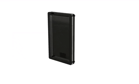
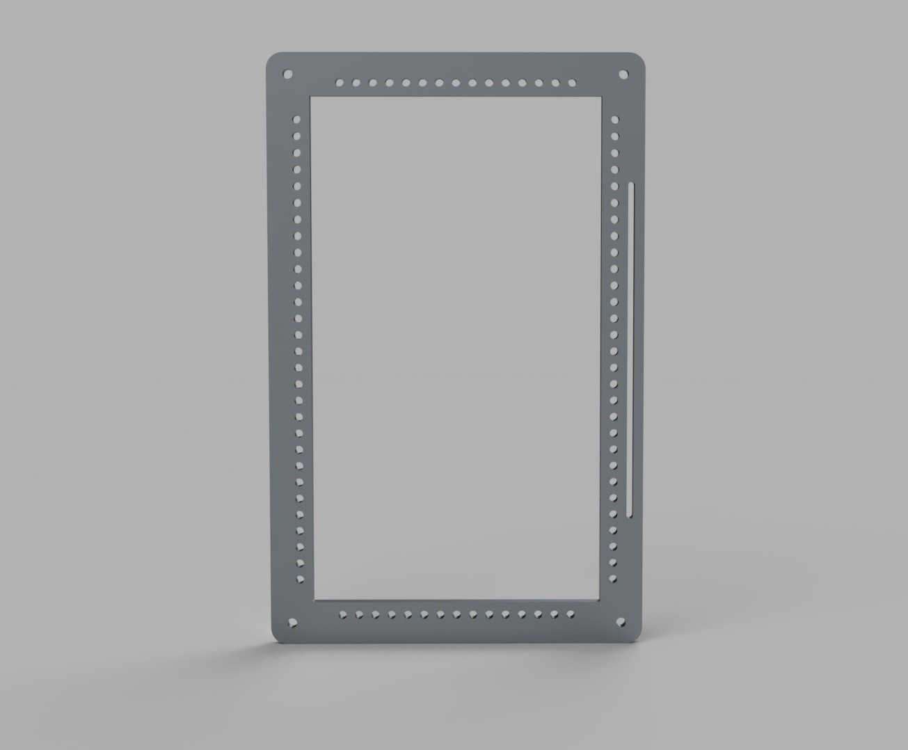
The frame is made out of 3 major pieces at the moment and is hold together by 4 screws (that might change as it is likely that is not stiff enough on the long side of the tablet).
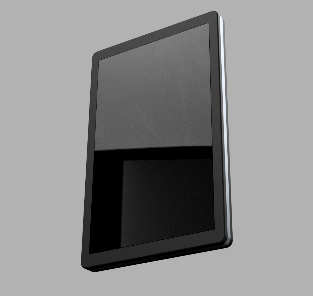
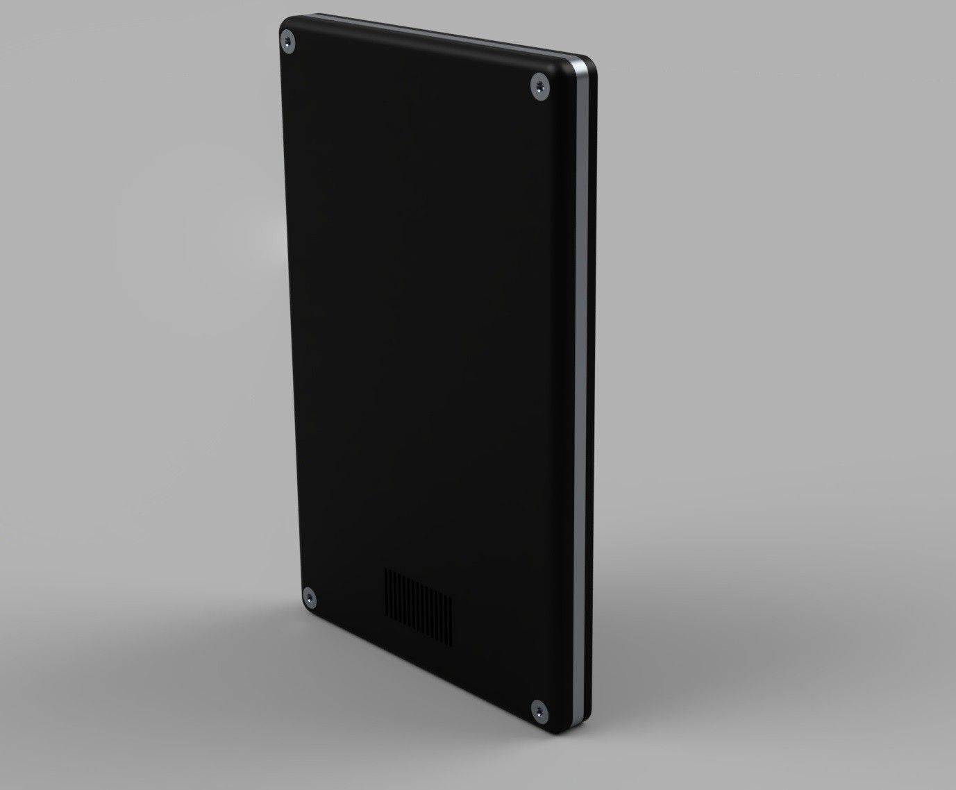
Here an exploded view of the current design. Bare in mind that this is still largely conceptual and it misses some details like studs that will be needed for stability of the back f.e.
The back is hollow and offers room in addition to space the aluminium mounting plate already creates.
This gives me 7mm space for hardware at the moment. I might have to increase this to 9-10mm by increasing the tablet thickness but I would like to avoid it. At the moment the tablet would have a thickness of 14mm which is about 2012 era tablet thickness. Which is still absoultely ok for me. This makes the product more hacker friendly (and repairable!). If you are looking for a 7mm iPad you will probably just get an iPad...
The idea with the mounting plate is that it defines a mounting standard similar to that of expansion slots in a PC case.
It has M2.5 threaded holes which are spaced 5mm apart giving you a nice even grid of 5mm steps.
There you can attach small PCBs for the peripherals that you wish to use (as well as the mainboard through another small mounting plate that takes heat away from the SoC to the large mounting plate).
The mainboard will offer several FFC connectors that break out all relevant peripherals. So each peripheral will connect to the outgoing connector through a flat flex cable.
This makes the mainboard itself very compact and you have the total freedom of where you want to have which functionality!
The only thing you would have to re-do is the plastic backplate. There are two options here. Have this be constructed out of one large back part and several smaller spacer parts that you could put between peripheral PCBs to close up the sides.
Or you have a single piece and you will have to print or mill yourself a new one.
From a product perspective I might offer both options. The latter looks much nicer, the former is more hacker friendly but actually very cheap to produce. It would actually make it possible to laser cut the whole assembly.
Here are some renderings. I'm still missing some dummy PCBs, I will add those in later to make it clear how the whole modular peripheral thing is supposed to work.
Discussions
Become a Hackaday.io Member
Create an account to leave a comment. Already have an account? Log In.
With your new processor target, I think you may end up needing something which can dissipate some heat, and some surface area to dissipate it over. The back cover may be the logical choice for this.
Are you sure? yes | no