The past weeks were spent designing the CPU schematic, and optimizing the available microcode instructions. The CPU schematic is now in the file section.
As a reminder, here are the hardware registers:
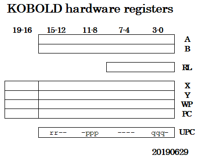
The registers A and B are always loaded at the same time (with the same data). The B register contents can be stored in memory (and can also be shifted left or right). The A register is connected to the input of the ALU.
The UPC (micro-programcounter) register will contain the 'user' instruction. Two 3-bit fields <ppp> and <qqq> can be used to select a source- and destination register with base address WP. The 10 remaining bits select an address in the microcode storage. Two of the remaining bits (the <rr> bits) can also select a displacement for memory access with pointer X or Y.
There are 3 classes of microcode instructions. The first one is register load/store:
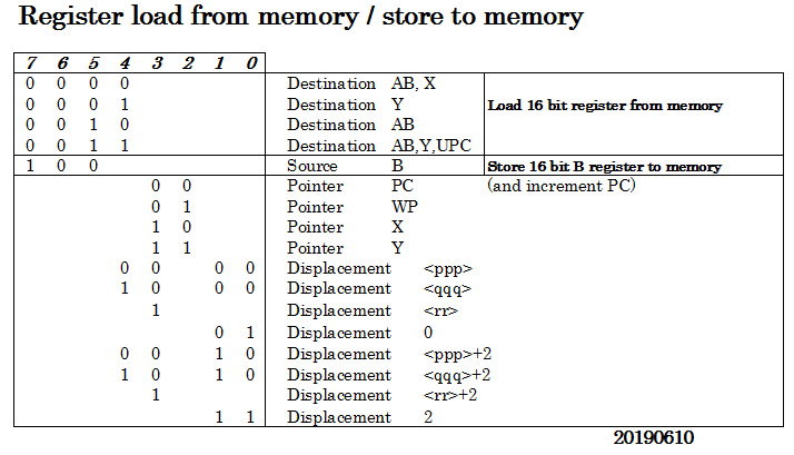
The user registers R0-R7 are addressed as (WP+displacement). For the displacement, the <ppp> or <qqq> register field in UPC can be chosen, these will be at addresses 0,4,6,8,A,C,E. The microinstruction has the option to add 2 to the displacement. This makes it possible to address 32 bit data (in memory or WP-based registers) in two 16-bit chunks, or address 16 word-sized registers instead of 8.
Note that when the instruction is loaded into UPC, it is also loaded in AB and Y. Why ? When the instruction contains immediate data, it is directly available to the ALU to do calculations. If it is an immediate byte load, the byte is already in the B register and can directly be moved to the destination.
The destination register can not be the same as the pointer because pointer register is a latch and not a edge-clocked flipflop.
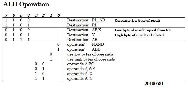
The RL register is used to temporary store the result of the ALU for low bytes. When the ALU calculates the high byte, the high byte will be combined with the low byte that was stored in RL, and the 16 bit result will be stored at the destination.
The PC can also be input to the ALU. This is useful for adding a constant to the PC (branch) or for obtaining the return address when doing a CALL instruction.
All microinstructions can be executed conditionally depending on carry, zero or other conditions (Actually, at each microstep a certain microinstruction is selected depending on conditions).
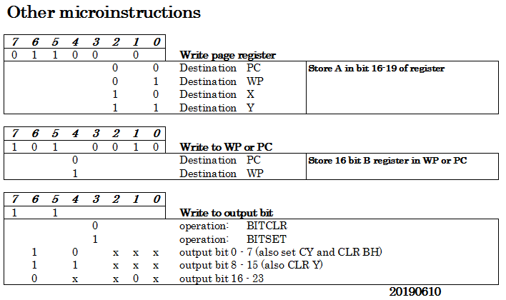
There are 24 output signals that can be individually set or cleared by microcode. These are used for:
- selecting the condition for conditional execution
- put the B register in a mode for shift left or shift right
- write only to upper or lower half of a memory word (for byte writes)
- video signals, like pixel count reset, sync outputs, video mode
- several other I/O
[edit: instruction codes updated 20190629]
Discussions
Become a Hackaday.io Member
Create an account to leave a comment. Already have an account? Log In.
Very nice! Like a modernised 6809 :)
Are you sure? yes | no