Close
0%
0%

Gesture FeatherWing

A daughterboard with a capacitive gesture sensor for the Adafruit Feather boards.

Similar projects worth following

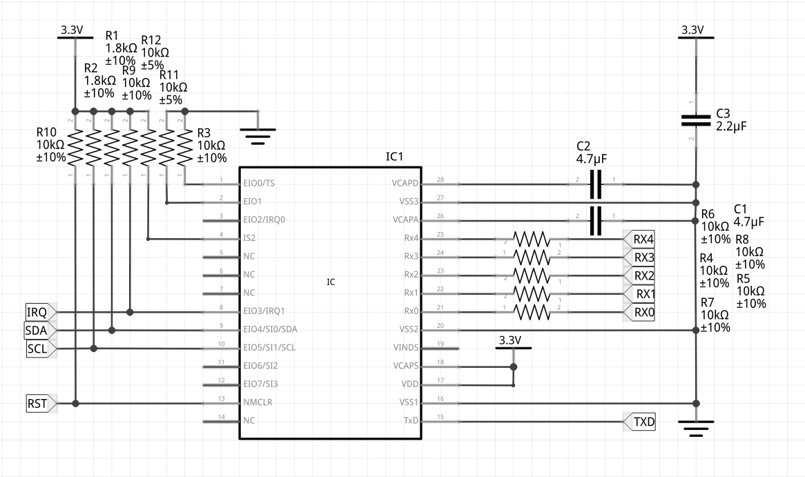
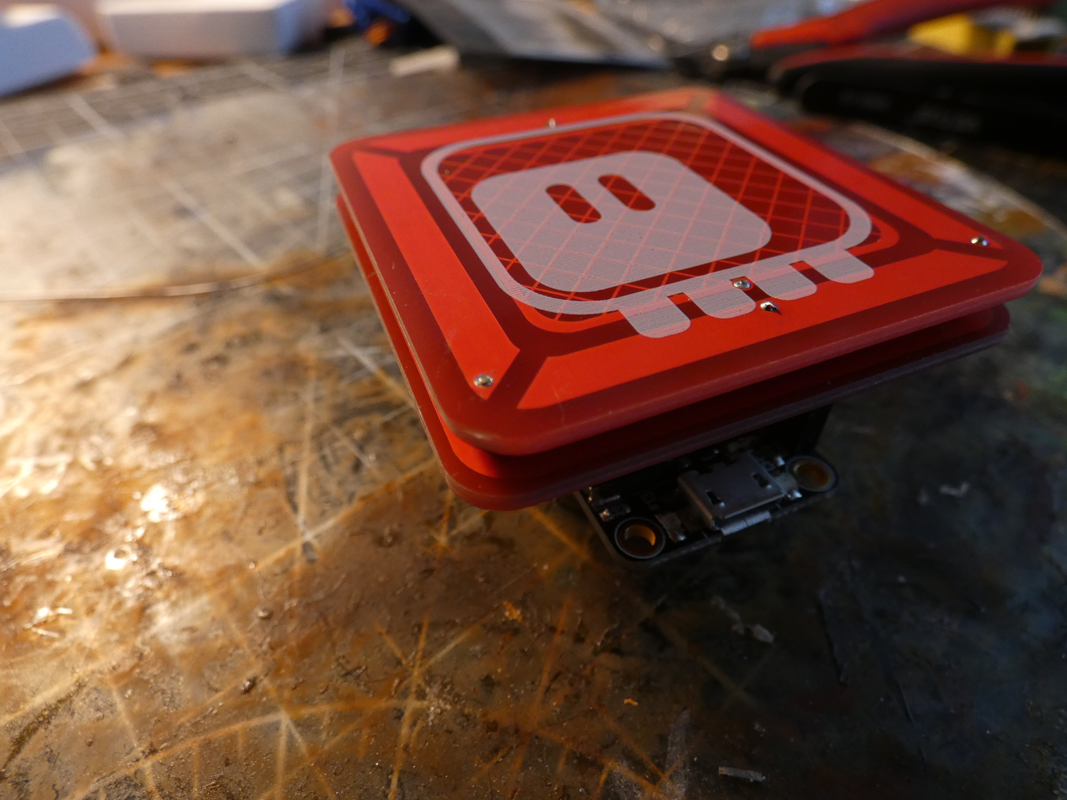
The MGC3030 is an integrated capacitive gesture sensor that could be used in a lot of projects, but unfortunately it has pretty strict requirements for how the capacitive surface needs to look like. This is an attempt at providing a ready solution, the sensor with the minimal viable surface, all as a single FeatherWing suitable for use with Adafruit's Feather boards.

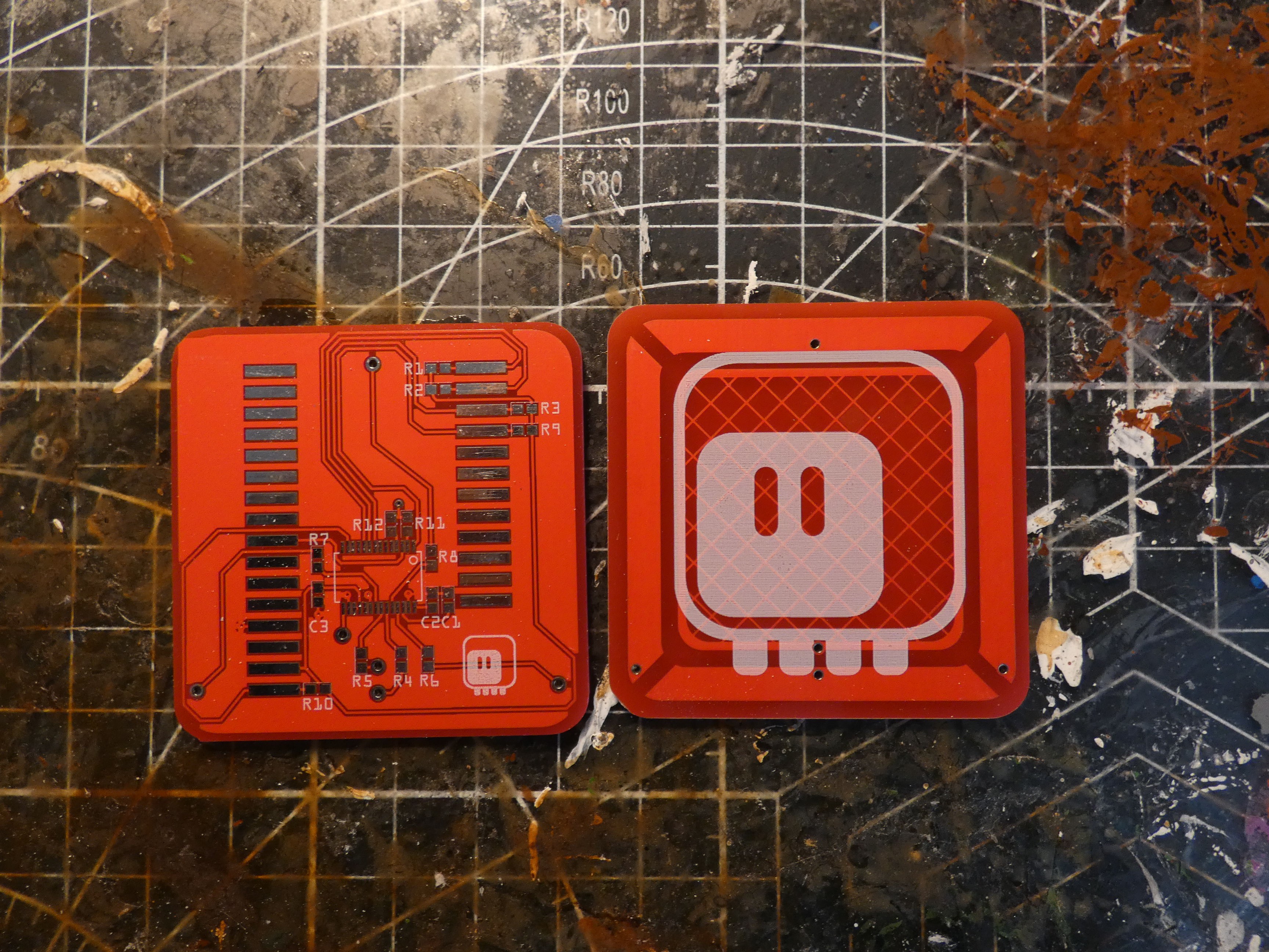
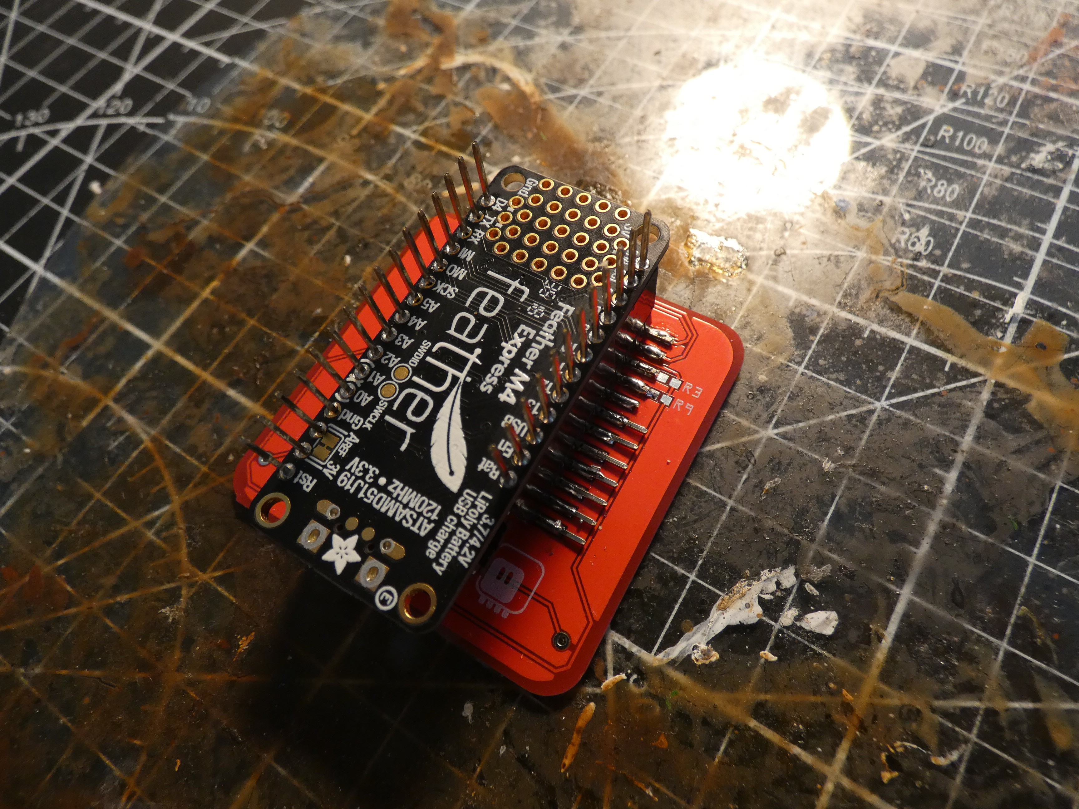
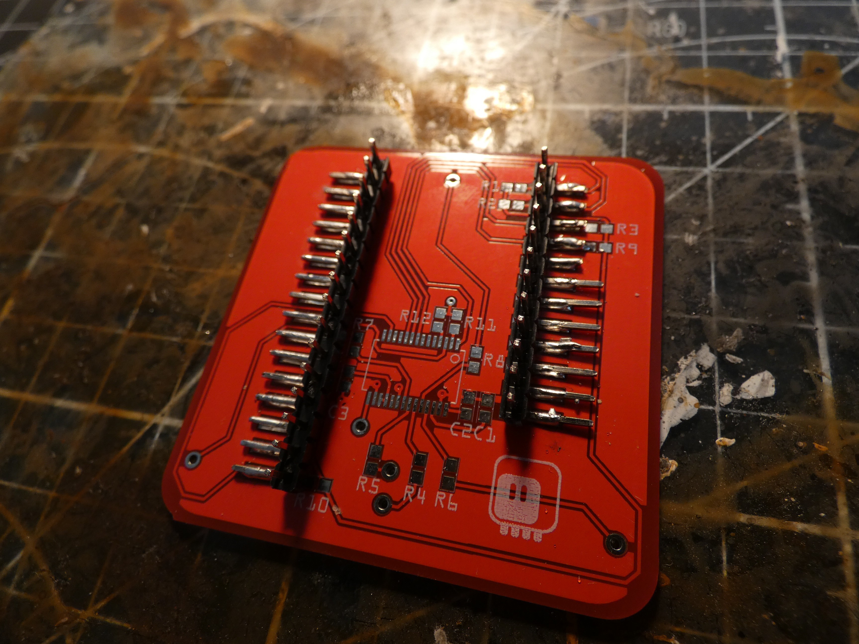
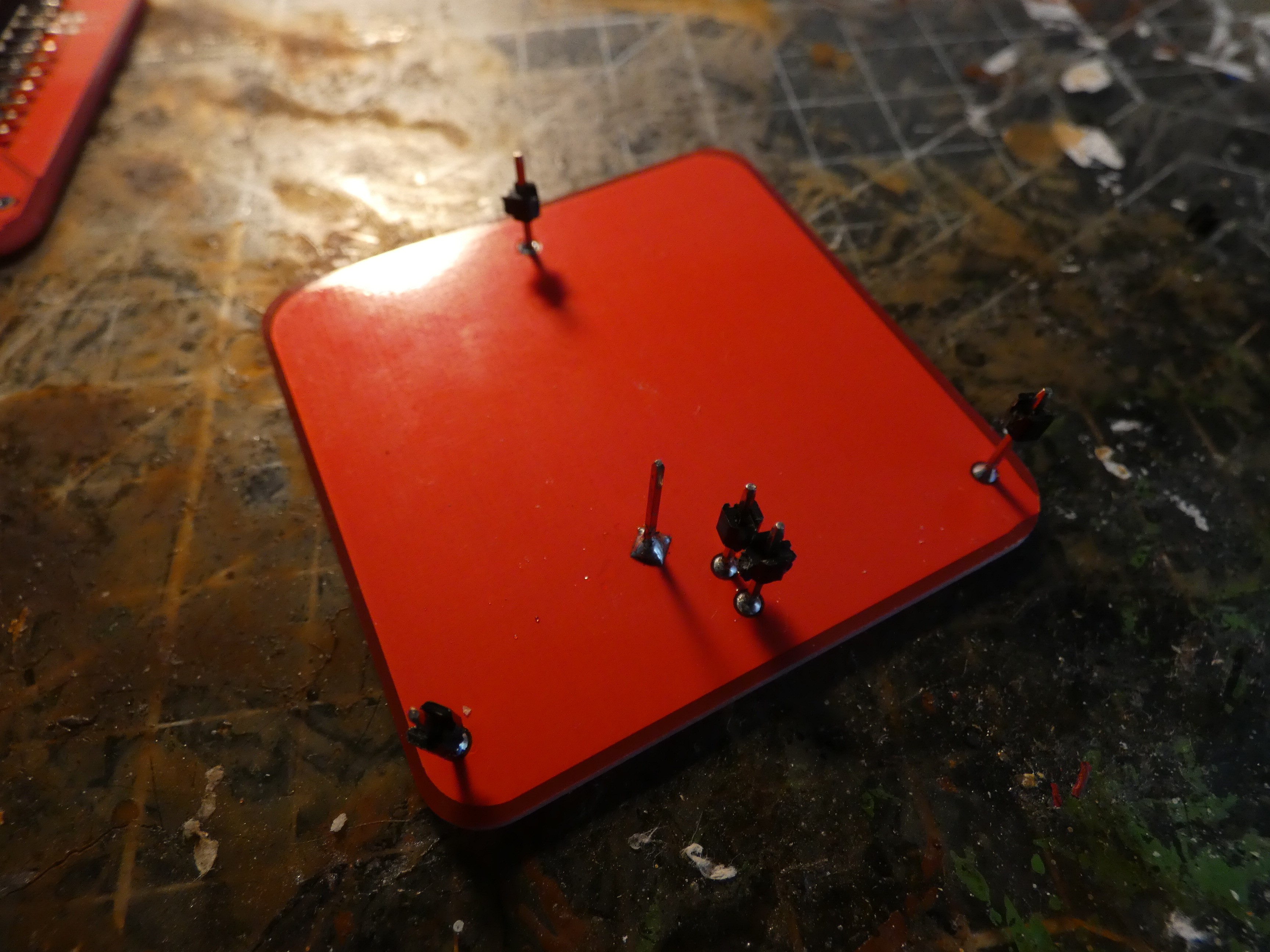
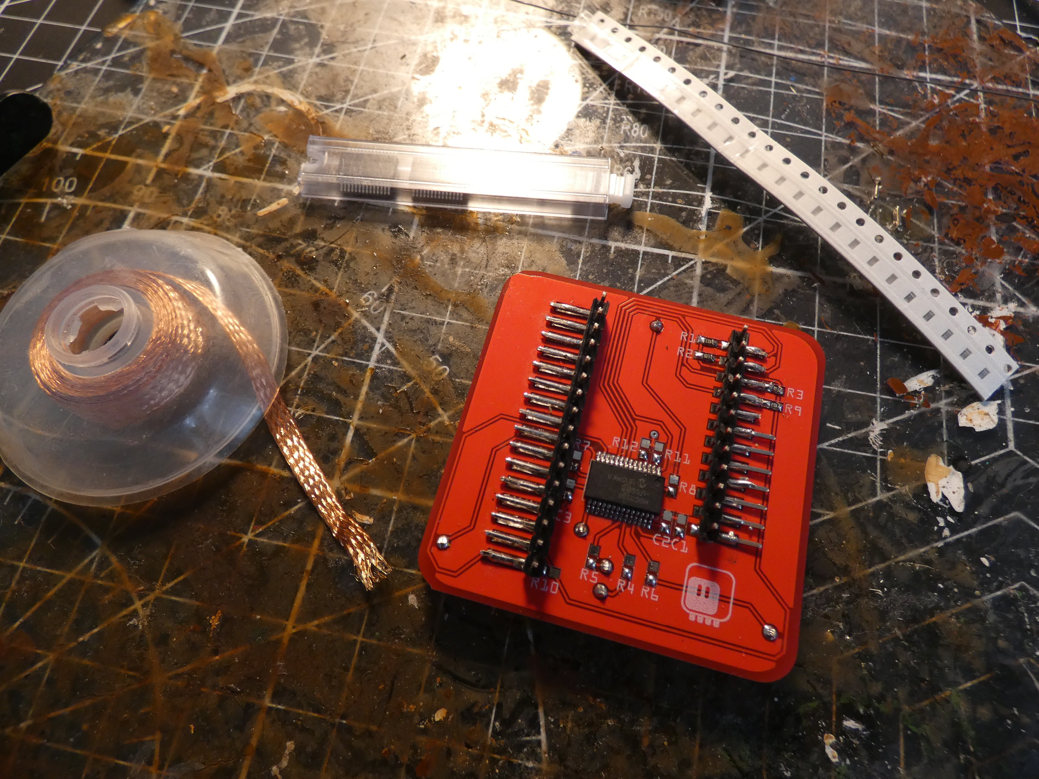
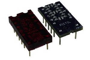
Because of the requirements for at least four layers that are spaced pretty far apart, this is actually a sandwich of two PCBs, connected with pin headers.

gesture1.fzz

Fritzing PCB design and schematic

x-fritzing-fzz - 43.60 kB - 12/31/2019 at 02:09

Download

  • 1 × MG3030
  • 10 × 10kΩ 0603 resistor
  • 2 × 4.7µF 0603 capacitor
  • 1 × 2.2µF 0603 capacitor
  • 2 × 1.8kΩ 0603 resistor

View all 6 components

  • Library

    deʃhipu12/31/2019 at 01:12 0 comments

    Today I decided to try and write a CircuitPython library for this sensor. So with a datasheet in hand I started with this simple code that is supposed to give me the raw data frames:

    import board
    import digitalio
    import time
    
    
    class MGC3030:
        def __init__(self, i2c, addr=0x43, ts_pin=None):
            self.i2c = i2c
            self.addr = addr
            self.ts_pin = ts_pin
            self.buffer = bytearray([0] * 26)
    
        def read(self):
            self.i2c.try_lock()
            try:
                self.i2c.readfrom_into(self.addr, self.buffer)
            finally:
                self.i2c.unlock()
            return self.buffer
    
    
    i2c = board.I2C()
    ts_pin = digitalio.DigitalInOut(board.D5)
    irq1_pin = digitalio.DigitalInOut(board.D6)
    irq0_pin = digitalio.DigitalInOut(board.A3)
    
    sensor = MGC3030(i2c)
    
    while True:
        print(repr(sensor.read()))
        time.sleep(0.5)
    

    The code works, except it shows me all 0s. What's wrong?

    Some more careful reading of the datasheet reveals that the chip is sold without firmware on it. You have to program it yourself, using attached software. The software is of course WIndows-only, so no way I can use it.

    Way to go Microchip! 

  • Discretes and Schematic

    deʃhipu11/02/2019 at 20:57 0 comments

    I populated the rest of the shield, and its seems to work — at least it shows up on the I2C bus. Further testing will require writing a library for it.

    I also fixed the schematic view, so that it can actually be understood. This is something I like about Fritzing — you can do the schematic later.

    While making the schematic, I also discovered that the version of PCB I have misses one connection (for the I2C address selection resistors), so I will need to bodge that in the prototype. The final version has that fixed.

  • Redoing It

    deʃhipu11/02/2019 at 11:04 0 comments

    I figured that as soon as I start working on it again, I will find the old prototype. It didn't work, but I did find the chips I had ordered for it, so I can just make a new one.

     There are two tricky parts to the mechanical assembly, first is the FeatherWing header:

    I'm using a feather to get the right spacing and alignment, ad then just soldering the angled headers to the pads. Finished, it looks like this:

    I had to cut some of them shorter, where the pull-up resistors for the I2C go. The current version of the PCB has that fixed, as the resistors are moved to the other side of the header.

    Next are the pins that connect the antenna to the main board:

    It takes some re-heating and aligning them to fit them in their holes, but the end result looks good:

    Next comes the chip itself:

    Now I need to check the values of all the discrete components in the datasheet and solder them, and it will be ready for testing. That will probably happen in a week from now, because I will be travelling, and I can't take it with me.

  • Lost in Time and Space

    deʃhipu11/01/2019 at 20:23 0 comments

    I started this project quite a while ago, and it was an unlucky one — always when the parts arrived, I was in a bit of slump, busy with some urgent thing, travelling, or just simply burned out. So the progress was slow, and I only took it as far as assembling and soldering the whole thing — I didn't have the energy to actually write the software to test it.

    And now I'm bringing it back from the dead, so to speak, to enter it in this contest, but... I can't find it. I clearly remember assembling the prototype, but it's not anywhere in my drawers or boxes. I found the un-assembled PCBs, so I could get another chip and start again, but I would much prefer not having to do that.

    I guess I will need to do a proper cleanup of my workspace.

  • PCB Design

    deʃhipu11/01/2019 at 19:52 0 comments

    To avoid paying extra for two PCB designs, both layers of the sandwich are connected at the corner — they have to be cut manually for assembly.

    The design above has the copper fills removed for clarity. The antenna pretty much follows the recommendations from the datasheet. The traces going to it are kept as short as possible.

    To avoid puncturing the ground layer, the connector for the Feather is made out of an angled male header, soldered SMD-style to the board. In a final design, a proper SMD header could be used instead.

View all 5 project logs

Enjoy this project?

Share

Discussions

Similar Projects

Does this project spark your interest?

Become a member to follow this project and never miss any updates