 Lucy Fauth
I don't want to talk too much about how tesla coils (https://en.wikipedia.org/wiki/Tesla_coil), and more specifically dual resonance solid state tesla coils (DRSSTC) work, as there already is lots of great literature on that (https://www.easternvoltageresearch.com/documents/book_drsstcpreview.pdf).
Basically, a tesla coil consists of an air-coupled transformer with a very high turn ratio. Low AC input voltage is transformed to high AC voltage, that is, in case of the dual resonance system, additionally amplified by electrical resonance effects. This high voltage is concentrated at a small tip, the breakout point, where the local field strength it high enough to ionize the air and create the arc.
We can separate the design in two parts, the passive transformer itself, and the electronics driving it. Let's start with the transformer first, as this explains some of the design choices for the driving part.
Most of you probably already have seen a tesla coil

(cc by Johannes Müllers)
These devices are usually smaller than 1m in height, but almost always bigger than 10cm. This has a very good reason: As the transformer has no core other than air, and there is some limit to the number of turns the coil can has (usually in the range 200-1000), the secondary resonance frequency (the frequency of the LC oscillator defined by the inductance of the secundary windings and the capacitance of then top electrode to ground) is only defined by geometry. For a 30cm coil, this would be in the range of 200-300kHz.
Here lies the first problem: Building bigger tesla coils is actually easier than a very small one. For DRSSTCs, the power electronics driving the transformer is usually based on IGBT switches, sometimes MOSFETs. But even with very modern Si-based switches, the switching losses increase massively at a frequency >1MHz. For reference, most motor controllers use 15-25kHz. Your laptops power supply no more than 200kHz. My coil design is at 2.6Mhz.
Usually, you use isolated magnet wire around a plastic tube for the secondary coil. This has the obvious advantage that as the voltage increases towards the top of the coil, also the distance towards the sensitive power electronics and primary windings on the bottom increases. However, manufacturing these coils is a lot of hand work. You can't just buy them in arbitrary quantities.
PCBs, however, have become super cheap. You can get 10pcs 100x100mm dual layer pcbs for $5 at your Chinese manufacturer of choice. With 5mil tracing and 5mil spacing as required by most manufacturers, this gives you 190 turns on a 100x100mm pcb.
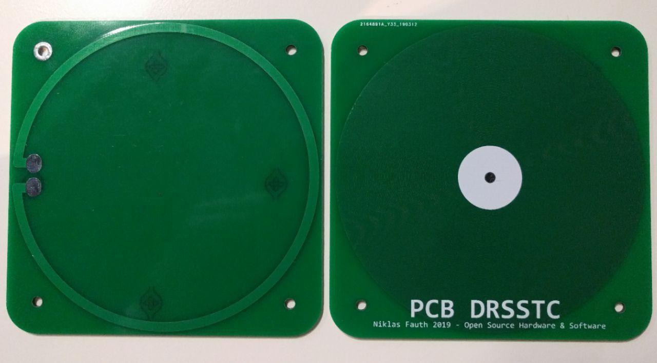
(left: bottom side with single primary winding, right: secondary winding with 190 turns)
There is nothing special really to these coils. It's really just a huge spiral going from the outside to the inside. I placed a circle of white silkscreen in the center the increase isolation a bit. The primary winding is a single turn. I also tried two and three turns (yes, I had to order new pcbs to test this, but it's just $5 so why not?) but as the secondary turns are already so low (190), you want to get maximum transformation ration. The primary winding is connected with pads to a XT60 high current connector, and the secundary winding has a pad in the center and a plated mounting hole on the low voltage side to connect the base point to the electronics for signal recovery and grounding.
Unfortunately, I was not able to create the gerbers for this in KiCAD as it interpolates circles with very bad resolution. I tried a svg to gerber converter but that also failed. I ended up booting my Windows VM and just used Altium Designer to create the files. Luckily, I did not have to change these files a lot, and you can find the gerbers on GitHub.
I ordered my coils at jlcpcb. They rejected the design because it failed the audit. Technically the design is perfectly within spec, however it is somewhat relatable: You're requesting 33m of thin parallel wire that cannot have a single short or open connection. Eventually I was able to convince them to make the board under the condition that I will not complain about the quality afterwards. Also, they did not make a e-test. However, checking the boards yourself is pretty easy: Just compare the resistance and inductance between the boards. If the resistance is ca 180 Ohm, there is no open circuit. If the inductance is very low compared to other boards, the coil has a short winding and is unusable. From the 70 coils (10 per design revision) I bought so far, only one had a short.
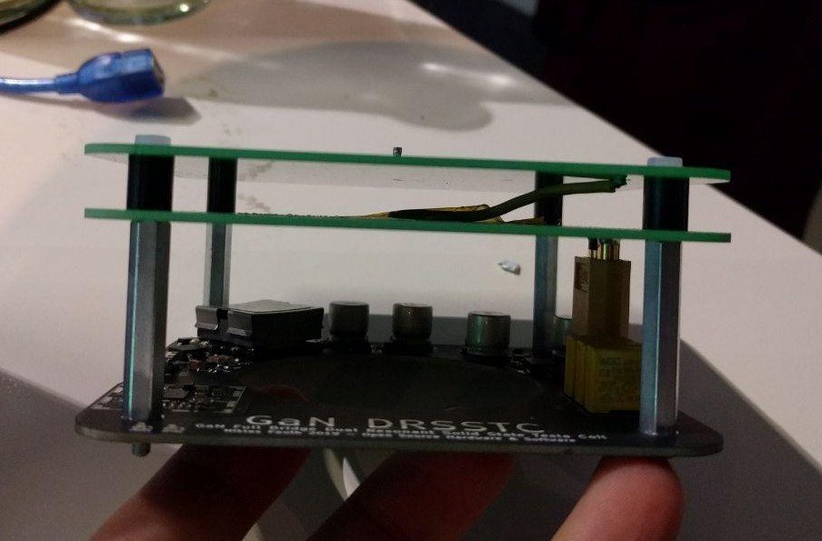
I'm using two coil pcbs stacked above each other. You can also use the design with just the bottom coil, but then the maximum discharge length is shorter (only 3cm) and the resonance frequency is much higher (4MHz), causing more switching losses. The two coils are almost identical, the only difference for the top board is that it does not have the primary winding on the back.
I also tried using a single pcb for all three coils (primary on bottom, smaller secondary on bottom, large secondary on top) which I though was a pretty nice design. Unfortunately this design went up in flames because the full voltage of the bottom and the top of the secundary coil is located opposite each other only isolated by 1.6mm FR4.
Connecting the two boards with wire can also lead to issues. Still this is currently the preferred option. Make sure to use wire with good isolation. Keep it as short as possible so it doesn't touch anything. Make the solder joints on the pads perfect so the are perfectly round and have no spikes. Add some layers of capton tape as additional isolation or your coil looks like this:
(https://twitter.com/JanHenrikH/status/1116077294865481733)
The boards are separated by 8mm spacers, screwed together with nylon screws. The spacers to the power board have to be conductive and are 40mm long.
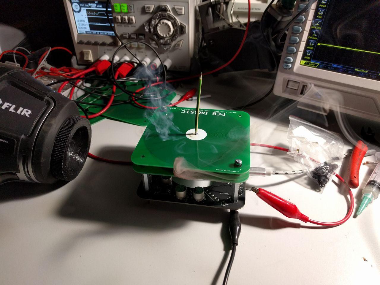
I'm using a spring pressure pin of an IC socket to plug in the wire used as the breakout point as inspired by Daniel (http://www.megavolts.nl/en/projects/tesla-coils/201-pcb-spiral-teslacoil-en).
This was the easy part and is mostly state of the art.
Discussions
Become a Hackaday.io Member
Create an account to leave a comment. Already have an account? Log In.