 Daren Schwenke
This project picks up where the P1 left off, but with some notable hardware improvements.
Blazing machine vision pipeline
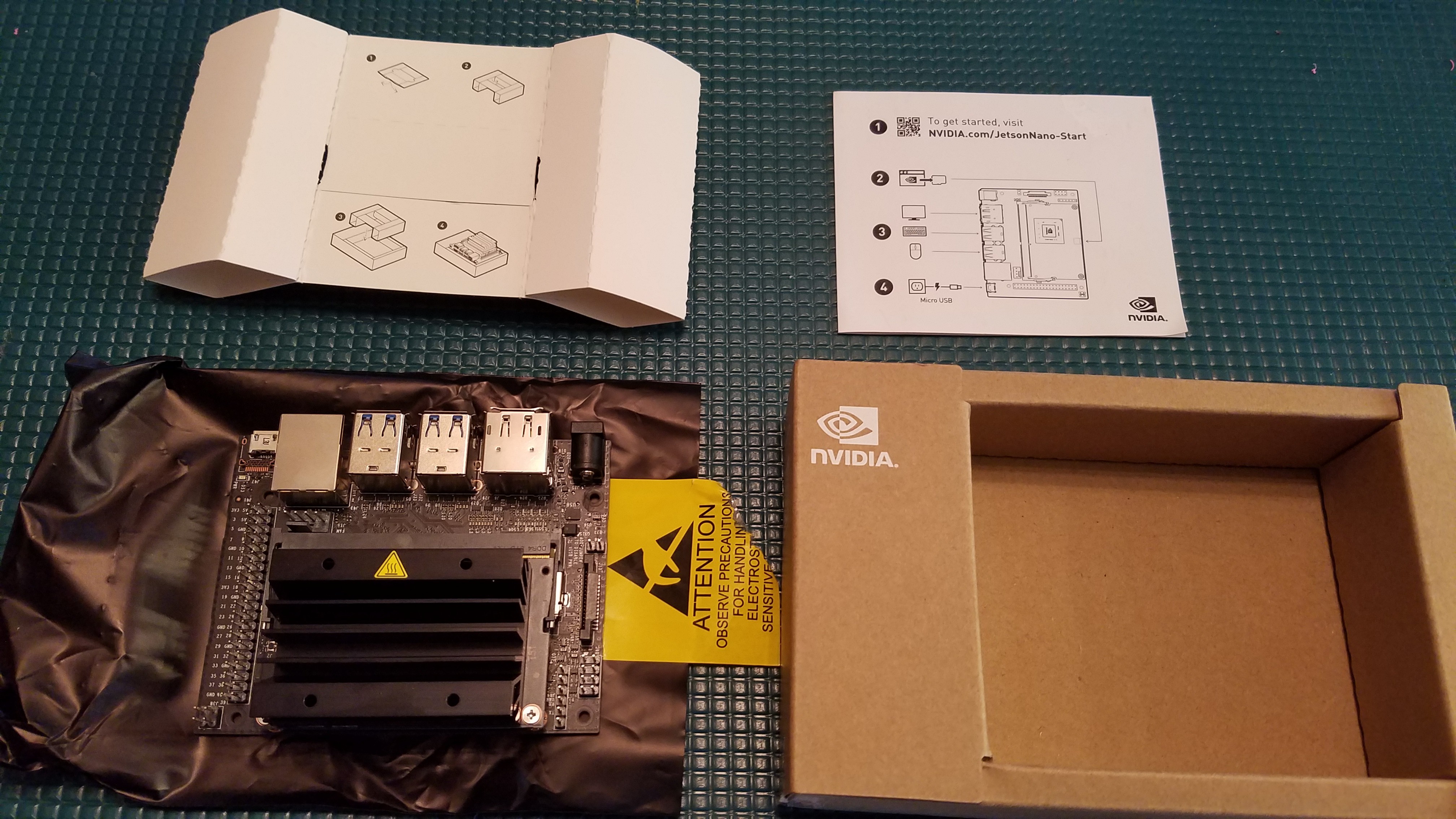
The Jetson Nano Developer kit has the perfect blend of speed, cost, and connections to make this project something really special. It has an onboard CSI connector which provides direct access to uncompressed HD video with extremely low latency (about 10x lower latency than a comparable USB 2.0 solution). Combine that with the powerhouse of machine vision acceleration that this provides, and this should be a very fast platform for running OpenPNP.
Top/bottom machine vision, with one camera
The same CSI camera which provides fiducial location and calibration (top vision) will also provide part rotation/part position checking (bottom vision). This is accomplished by the use of two tiny first surface mirrors mounted on a swingarm. The swingarm has a hard stop and the extended position is located at the apex of the rotational travel of the servo driving it. This provides a purely mechanical means to accurately position the mirrors at exactly the same position every time. The mirror can deploy and retract in 0.13s.
Ultralight part rotator
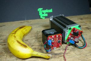
Part rotation will be provided by a small BLDC motor driven open-loop with sinusoidal drive, similar to how a BLDC camera gimbal motor operates. The torque required for part rotation is miniscule, so running it open-loop with no position feedback should be sufficient. If not, active feedback for rotational positioning can be added via a hall-effect position sensor. The sensors and magnet required would add about $15 to the cost.
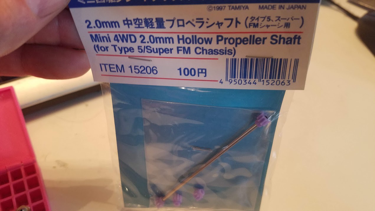
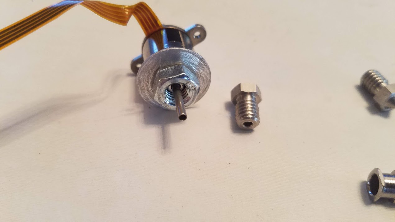
The BLDC motor I am trying first was originally designed to spin the color wheel in a DLP projector. It was relatively painless to replace the existing 2.0mm shaft with a hollow one. Having a hollow shaft is the simplest and most reliable method to pass the vacuum needed for picking the parts.
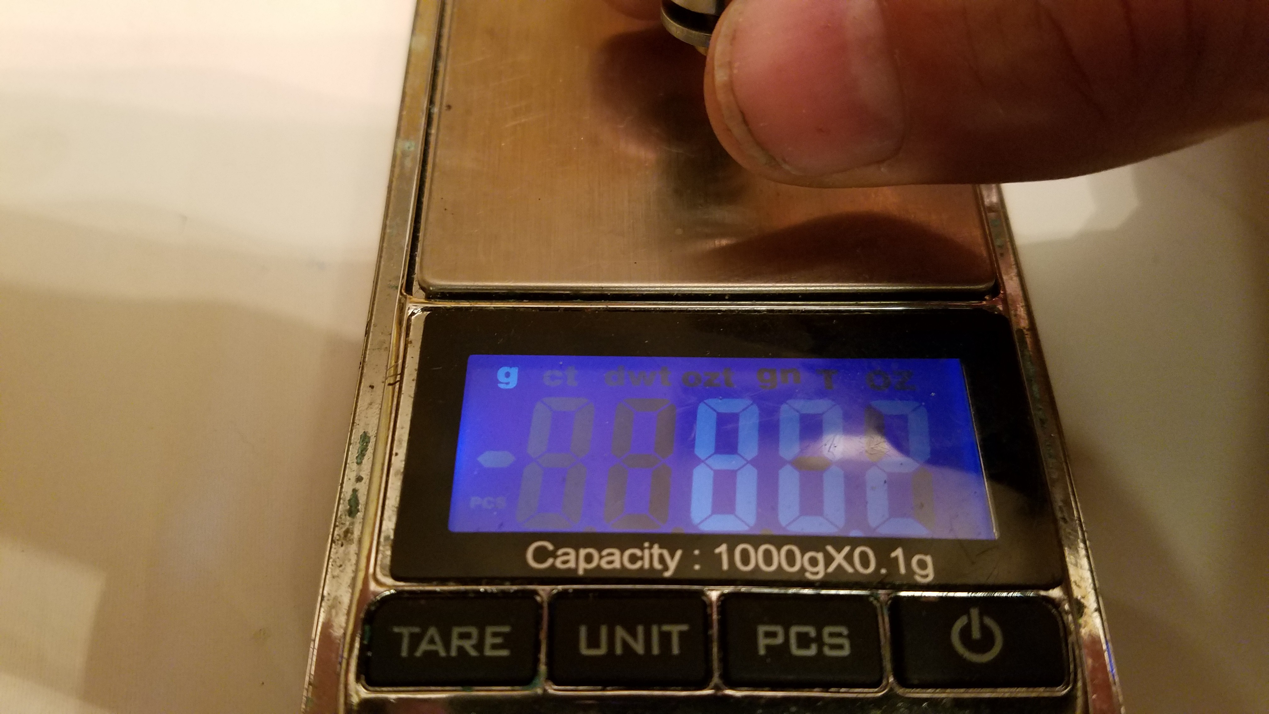
Many off the shelf small gimbal motors also implement a hollow shaft, but the lightest one I've found is 30g and perpetually 'out of stock'. I did find a couple smaller ones with a solid 2mm shaft weighing ~18g. However, the DLP projector color wheel motor only weighs 10.9g and has 9 poles and 11 magnets, so it is also suitable for providing the rotational resolution required.
Extensible,let's use that...
OpenPNP gladly interfaces with more than one motion controller, so this seems like the logical place for where your existing machine and the additional hardware required to make it into a Pick and Place machine, can come together.
For support of the basic electrical requirements, I've decided to put everything special required onto a single purpose-built add-on board now. This will need a BLDC motor driver, a vacuum sensor, at least one channel of logic level PWM for servo control, and a few channels of Mosfet driven PWM for lighting and vacuum solenoid control. I might as well include some additional PWM channels to make it easier to directly support a couple part feeders here as well.
Alternate electronics path
I have also thought about creating a 3 phase motor driver 'step-stick'. That would allow direct replacement of one of the motion axis step-sticks on a RAMPS type board. There are other 3 phase motor drivers which would fit in this form factor and could be married to an STM32 with just enough space to spare for mounting the required support components. Heat dissipation of the board itself would definitely be an issue if used at anywhere near the rated current of this chip of 5.5A. The target BLDC motor would not have this issue, but of course people are going to...
Read more »
 jcchurch
 Jrsphoto
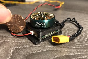
 Christopher Xu
 Matthias Hasenfus