 AlisonYao
Introduction:
This log is an update on the exploration on reflective surface in log 3 and a showcase of the very first prototype (Jun. 11 to Jun. 18). We plan to put the LED Matrix on the top and the IR receivers & emitters right below it. For prototype V1.0, which contains a place for both LED Matrix and IR, we used Fusion 360 to design and 3D printer to print it out.
A Followup on Log 3:
In log 3, we mention testing different reflective surface like using conductive tape. However, the outcome of conductive tape is not very good because it is too reflective and therefore cause more problem with distance sensing. The IR intensity is almost the same for a distance of 5cm and a distance of 10cm at the angle of 0 degree. So, we looked for a less reflective surface and sprayed the surface to add a metal-like texture.
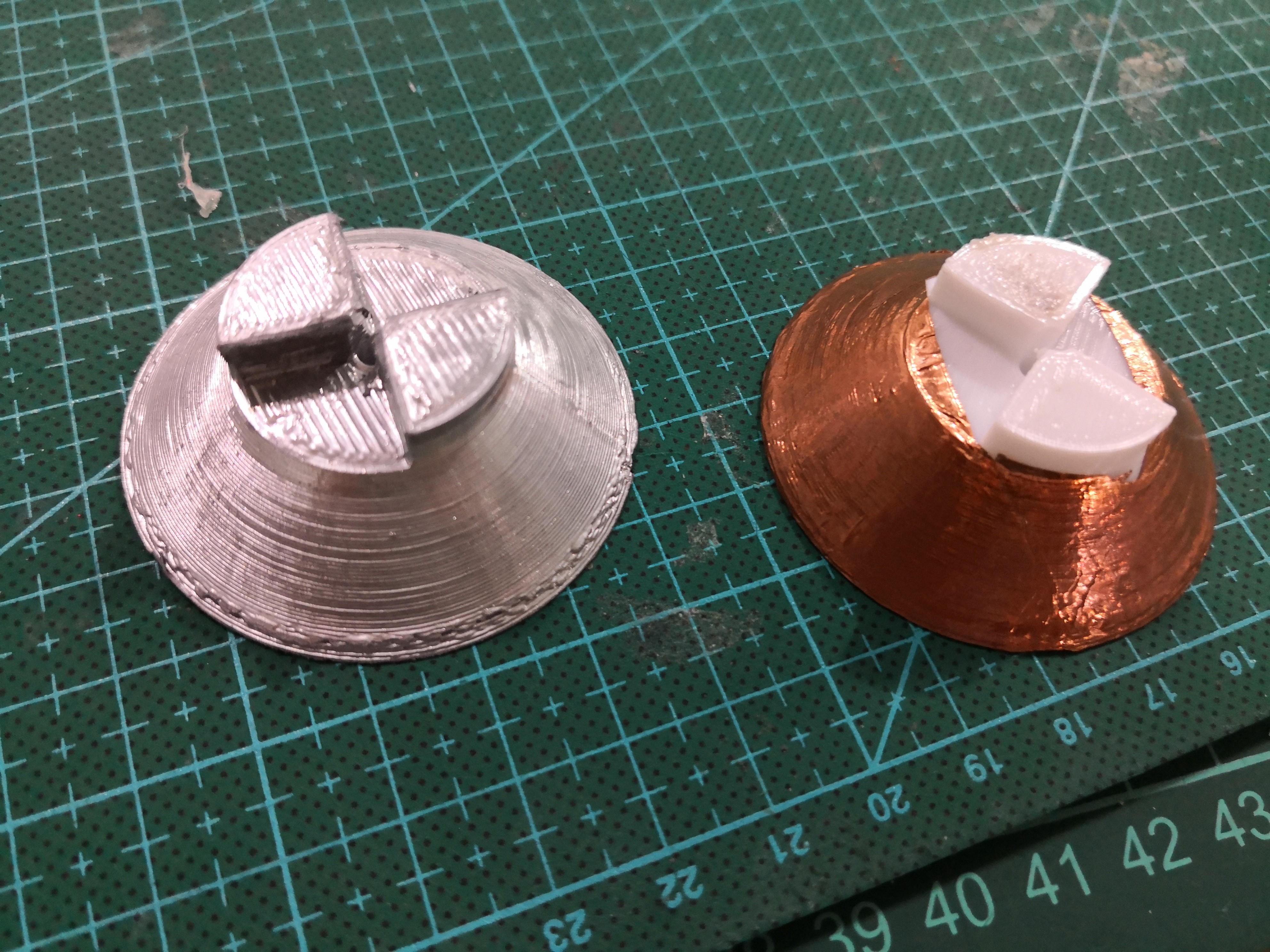
The picture above shows two reflective surfaces.
Prototype:
Design:
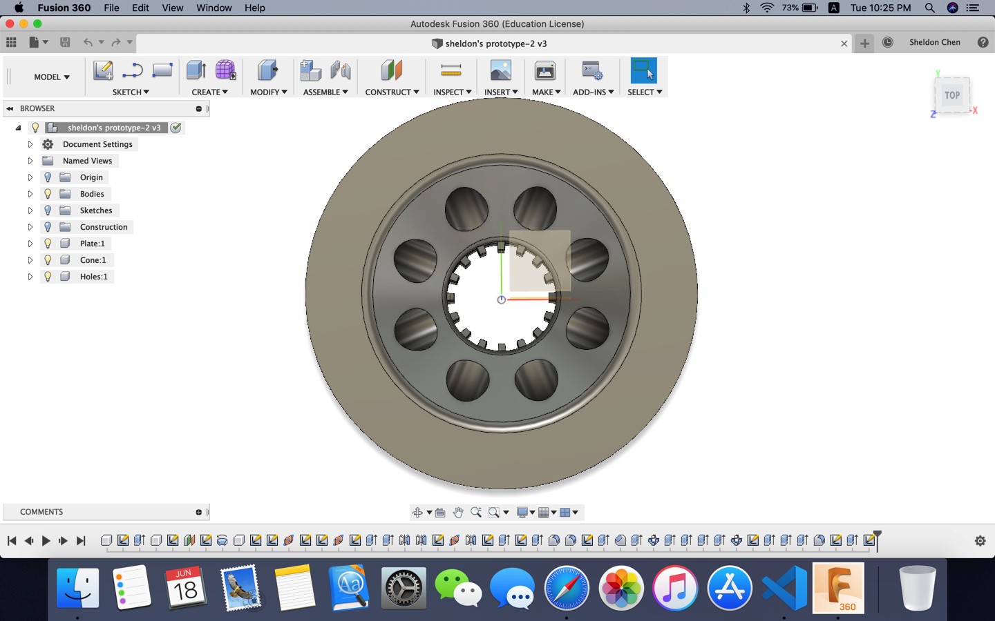
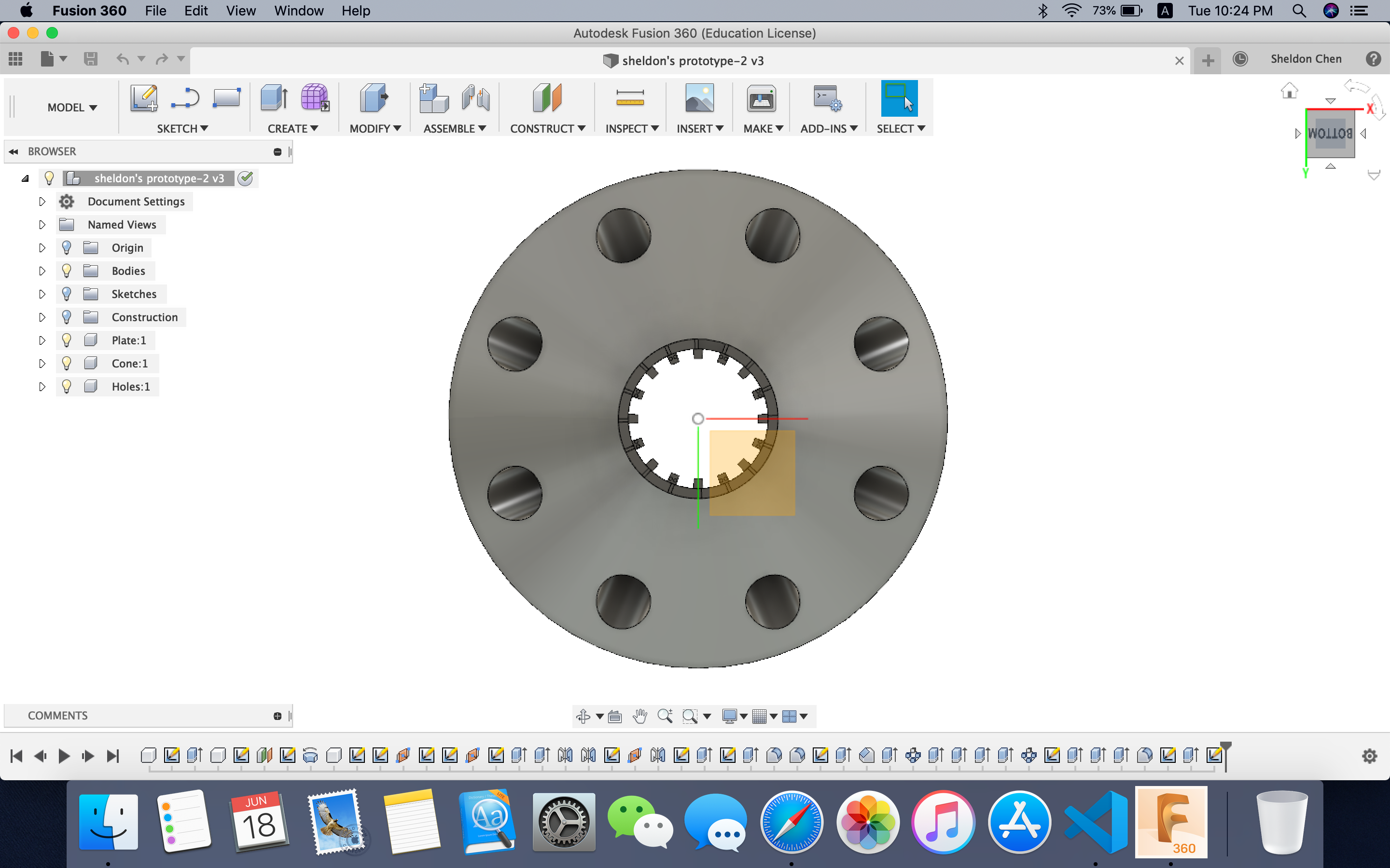
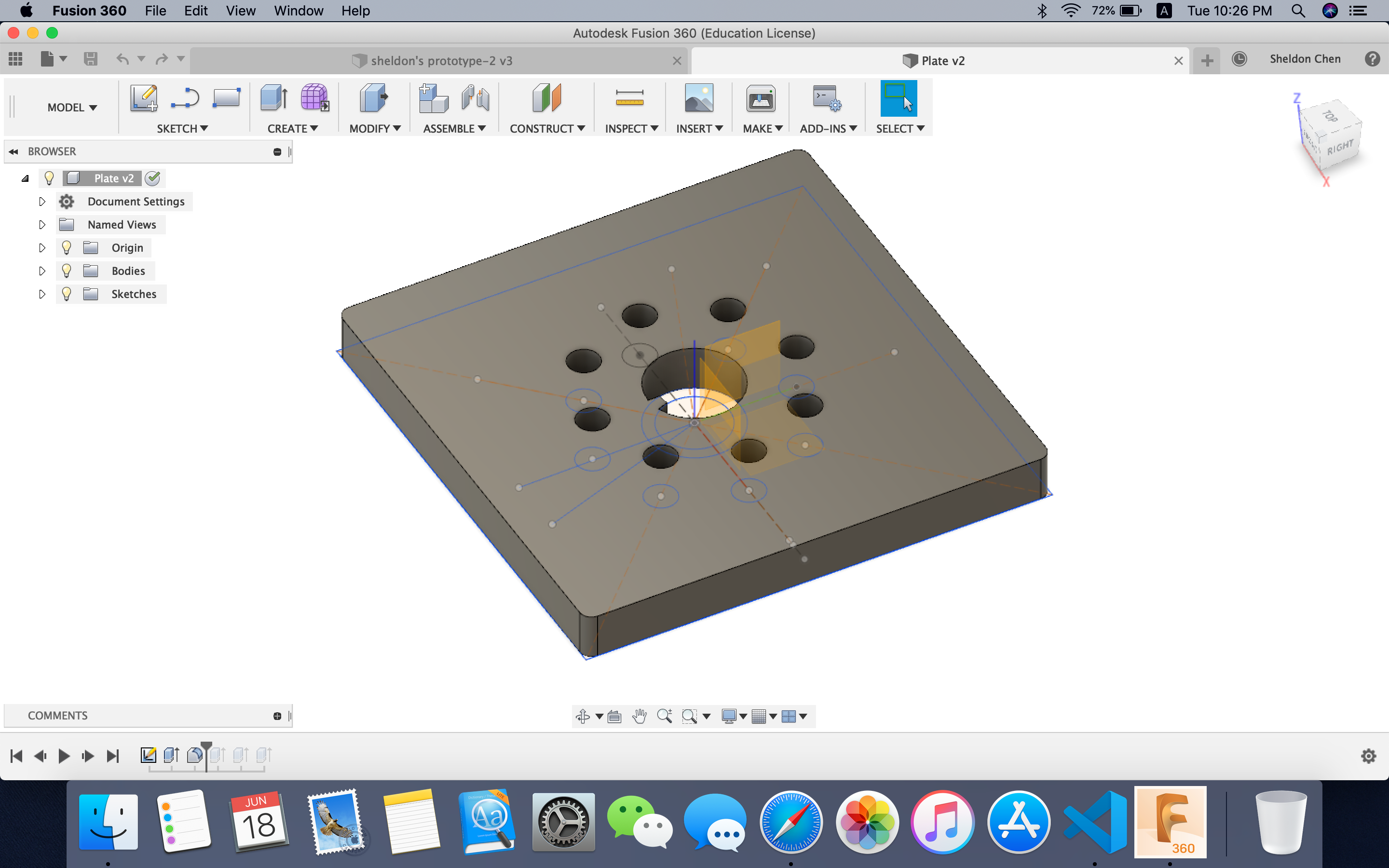
We used Fusion 360 to draw the 3D sketch of the prototype, which consists of three parts. All three parts need to able to be fixed onto one another without using hot glue. Here, we present the three parts from the bottom up.
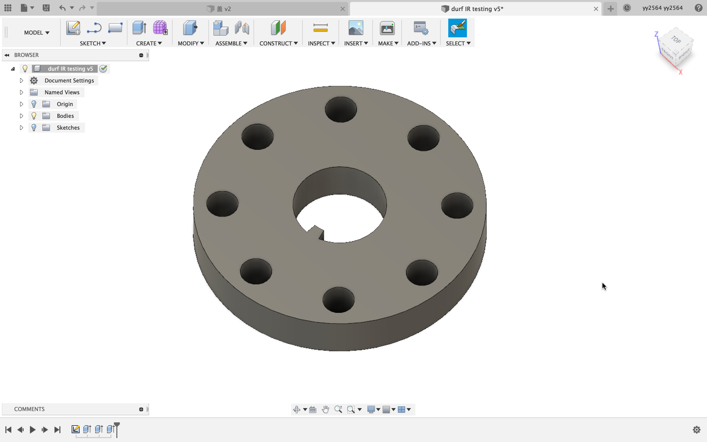
The first part is the IR receiver holder. There are eight holes for eight senders in the shape of a circle. The diameter is currently 50mm. However, the distance between the center of each hole to the center of the big circle is kind of random. We are still trying to find the best distance.
The second part is the IR emitter holder. Its shape is made according to the first part. So are the position of the holes. The big hole in the center is for the legs of the emitters. And the legs are separated based on the design.
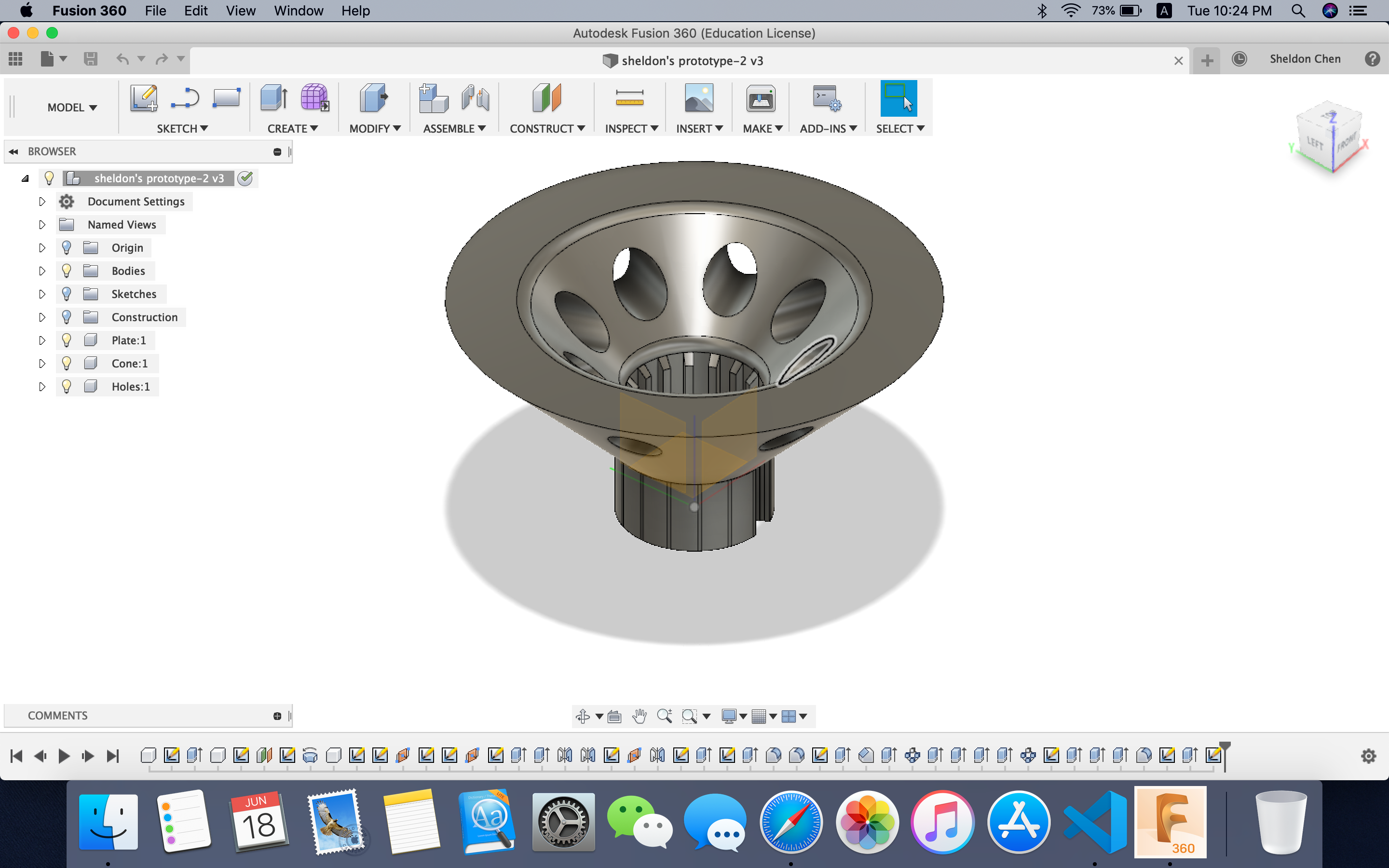
The third one if the LED Matrix board. It should be able to fit the LED Matrix perfectly and leave a hole in the middle for the wires to go through. Also, there need to be a slot for the wires on the board.
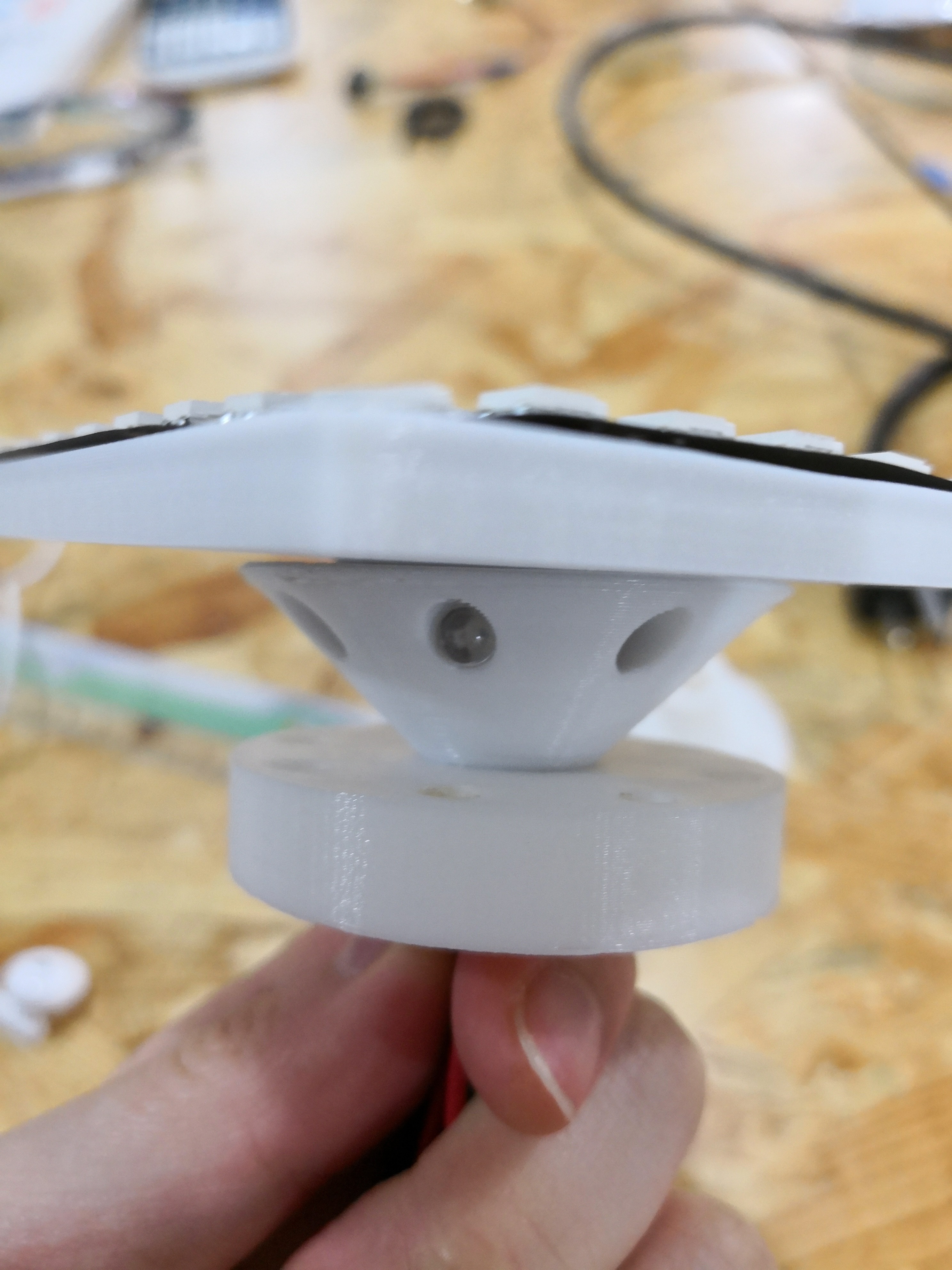
Implementation:
We printed all three parts out and assembled them.
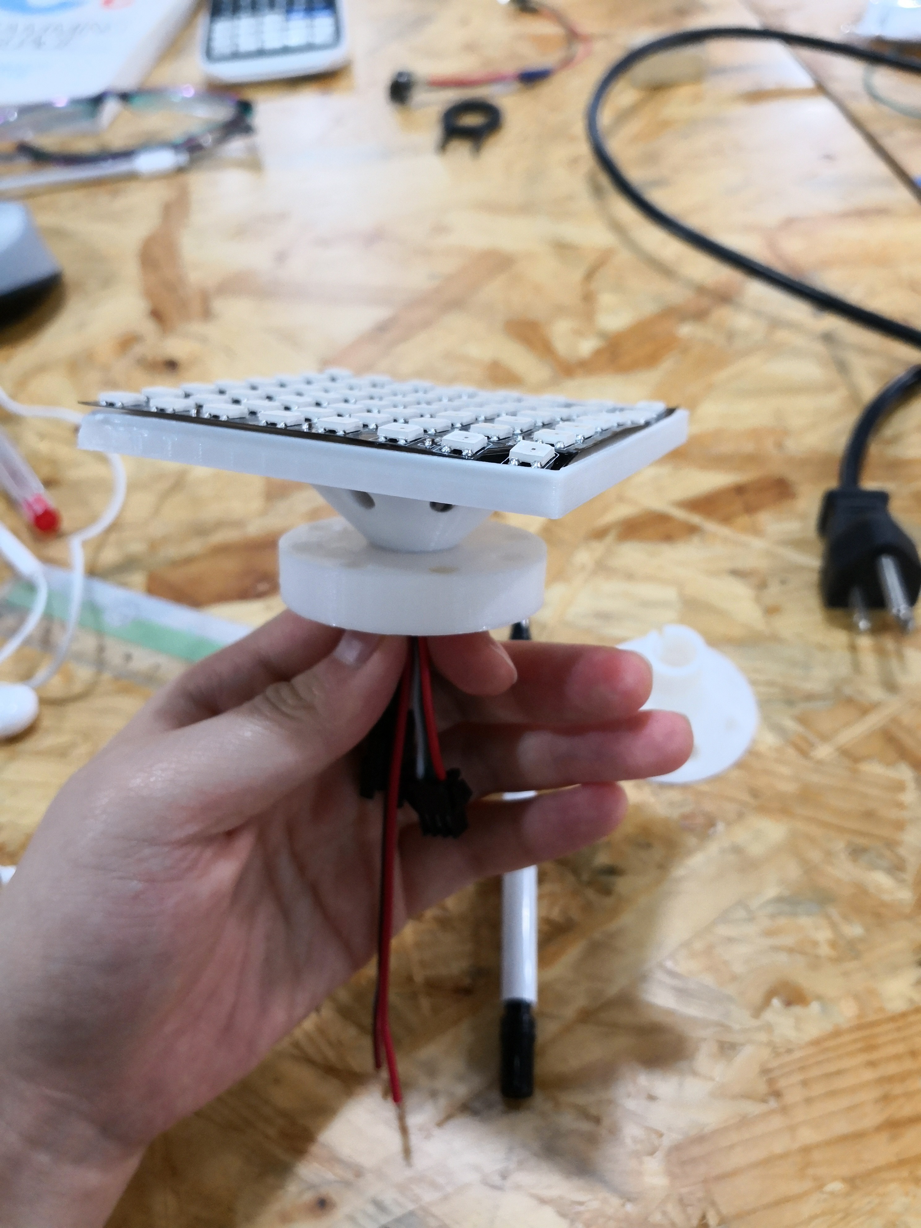
The prototype is good in many ways and we expect that there wouldn't be much big changes.
Further Improvement:
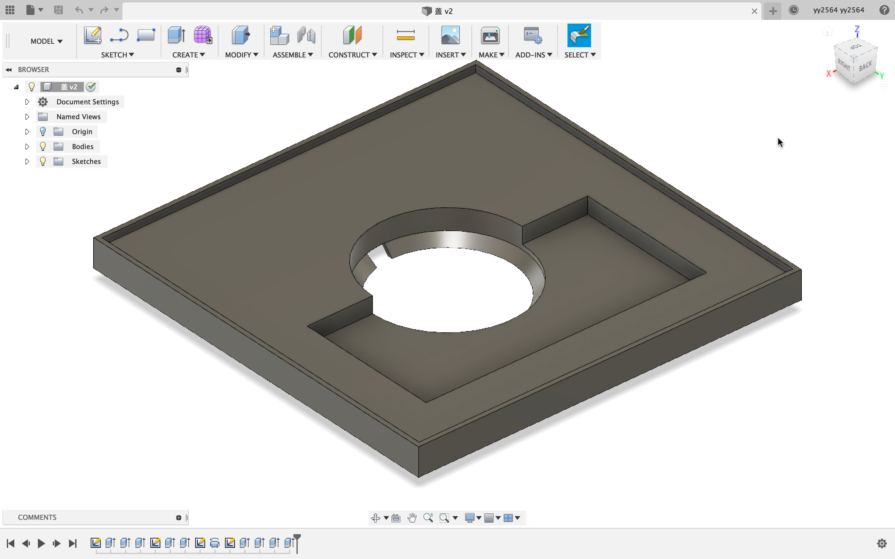
1. To fit the size of the robot, which is 8cm*8cm, we might expend the first part as below.
2. The distance between the center of the receiver and the central hole needs further exploration and more tests to find.
3. We need to redesign the way the second and the third part fit together. We expect to use two poles sticking out on the board and two holes on the IR emitter holder.
Discussions
Become a Hackaday.io Member
Create an account to leave a comment. Already have an account? Log In.