 nh8157
Hardware
We received our first PCB prototype on Monday (let’s call it v0.1.0 for Swarmesh 2020)! We assembled the PCB and immediately we could see that there were several improvements to be made for the next version.
- The first of which is the addition of a boost converter DC/DC for the motors, stepping up the 3.7V to 5V. This would provide more power to the motors since the motor driver consumes some current.
- Another issue was the pull-up resistors near the motor driver which caused a huge problem where the robot wouldn’t power on with solely battery power. Fortunately, that was solved by replacing them with pull-down resistors.
- We also need wheel cutouts on the new PCB because the sides of the wheels are touching the PCB.
Other than these issues, the test board works well and the 3.7V battery is enough to power the robot (assuming the battery has a decent amount of juice). As for the wireless charging, the ones we had were not in the best condition and we bought new ones to test. These new ones charged a 3.7V battery from 2.7V to 4.2V in 5 mins which is very fast and might even be too fast. The wireless charging system we are planning to pursue is still under ongoing tests.

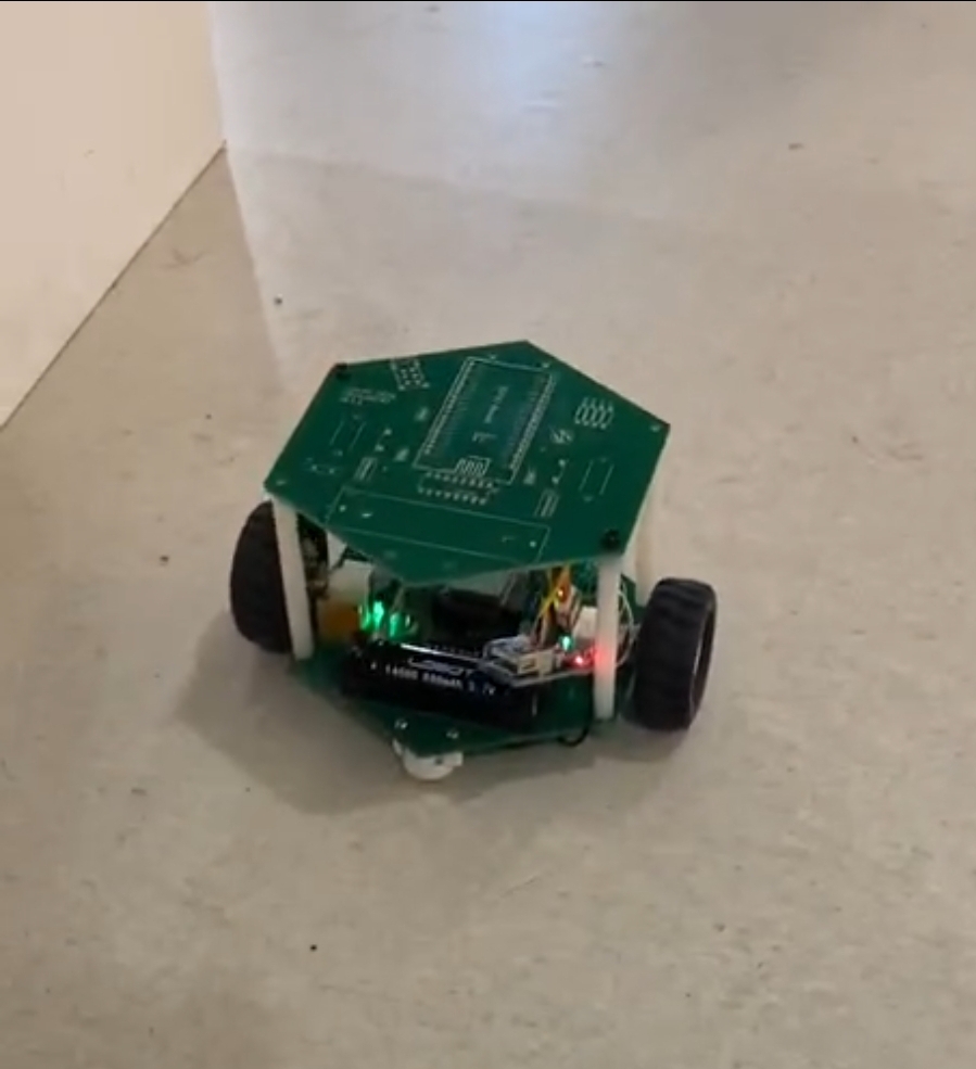
Figure 1a.
Figure 1b.
On Tuesday, we started planning and structuring our new PCB (v.1.0.1). Changes and additions are as follows:
4. ESP32 documentation recommends an output current of 500mA or more when using a single power supply. The MCP1700 LDO mentioned in the last post has an output current of up to 250mA while consuming only 1.6uA of quiescent current, a far lower current than the recommended output current for ESP32. When we employ the Wi-Fi networking functionality on ESP32, it will possibly trigger a brownout or other crashes. To be able to provide at least 500mA peak power for ESP32, we compared different LDOs and eventually settled on the AP2112K-3.3V LDO which has a maximum dropout voltage of 400mV, an output current of 600mA, and a quiescent current of 55uA.

Figure 2. LDO Table
5. We shrunk the size of the PCB to a hexagon with 50mm sides. Accompanying the change to a smaller PCB, we also changed the resistors and capacitors to SMDs. The switch will also be more compact in size. The standoffs are now M2.
6. We decided to remove the devkit and replace it with only the esp32-wroom-32d module and 6 pins for the programmer.
7. Pins for I2C were added which means we can also add an IMU to the robot.
8. Two touch pad sensors
9. Analog pin for battery level
10. Three leds: one for power level, one for charging, one for state of the robot
11. Two sets of pins for two reflective sensors
12. Five sets of pins in the front of the robot for 5 pairs of IR sensors. We used to have a mux to increase the number of analog inputs, but since we have enough analog (ADC1) pins on the ESP32, we refrained from adding a mux to save space.
In the following week, we will be receiving PCB v1.0.1 and assembling it. Hopefully, everything will work as intended.

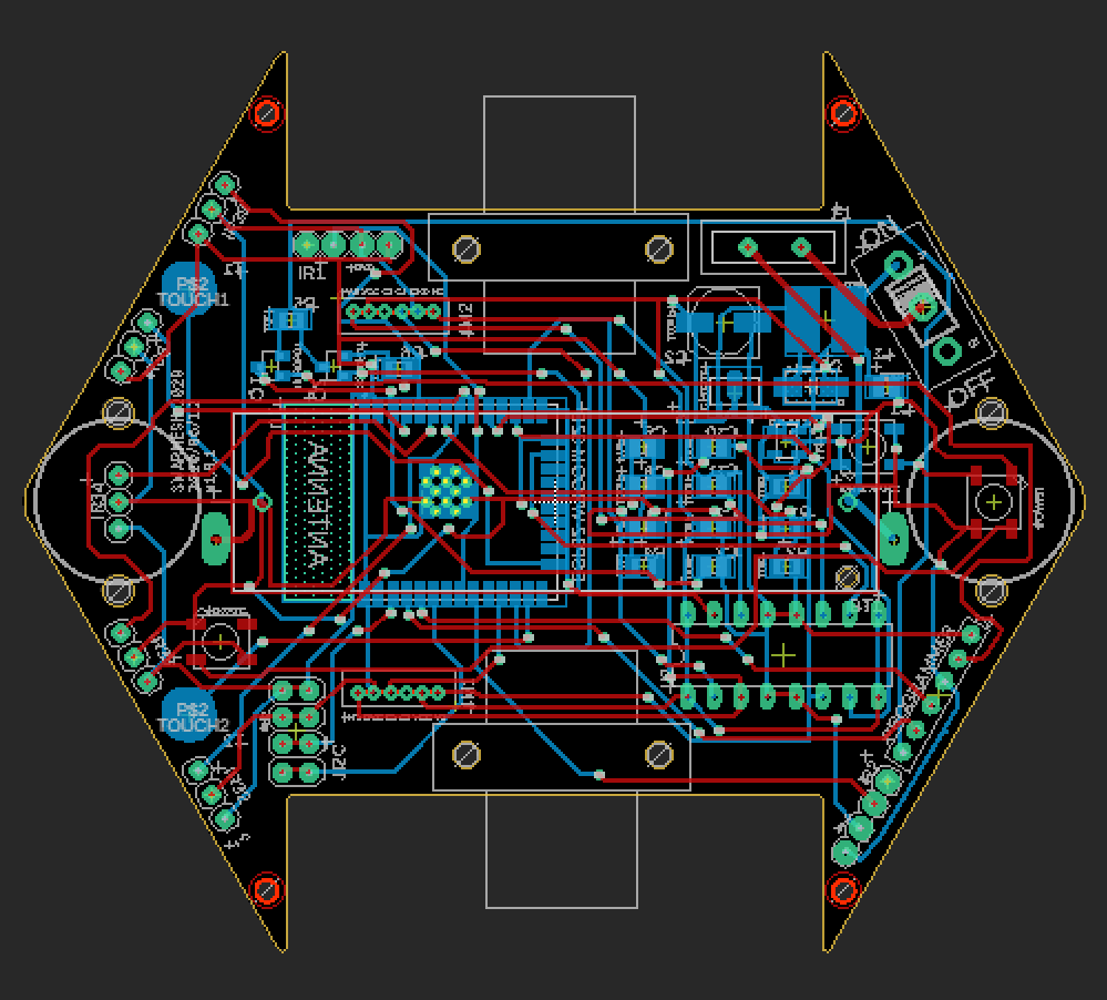
Figure 3. Schematic for v.1.0.1 Figure 4. PCB layout for v.1.0.1
Software
This past week has witnessed enormous software progress we made. Based on the camera system and tests implemented last week, we now can give the swarm of robots a list of destinations to go to, the robots would then figure out the destination they should go to.
The logic of the system follows the Finite State Machine shown in the last blog post. Robots would receive the absolute position of all robots as well as positions to go to in Json documents delivered by multicast. Each robot would pick the destination with the least Manhattan distance with regard to its current position. When a robot arrives at its destination, it would again send a multicast message specifying certain coordinates are taken. For other robots which also picked the same destination, they would pick the destination with the least Manhattan distance from the list advertised by the server. For robots that didn’t pick the same destination and have not yet arrived at their destination, they would delete the destination from their lists. If there are more robots in the system than the assigned destinations, robots that don’t have a destination to go to would go back to the spot before any task was assigned.
Same as the grid system in Manhattan distance, the robots always go in a straight line, turn 90 or 180 degrees when it needs to.
The above functionality was achieved with the code we wrote this week. Of course there are still potential bugs in the system; it would usually take a lot of time for the robots to go to their destinations. But in general, the system works.
In the coming week, we will work on
1. PID algorithm for the robots, so that the robot wouldn’t suffer from undershooting or overshooting when turning and moving forward.
2. Draft collision avoidance protocol, which we will discuss in other parts of the blog.
3. Put the collision avoidance protocol into the simulation platform.
We also did some literature review on collision detection and avoidance. We found two articles that are really similar to our project, which are “Multi-sensor based collision avoidance algorithm for mobile robot” and “Collision avoidance among multiple autonomous mobile robots using LOCISS (locally communicable infrared sensory system)”. Both of them, in the first place, gave us insights on which sensor(s) may be effective for us to apply to our own robots. Considering many other articles, sensors like cameras, IRs, ultrasonic, and etc. are commonly used in such a system. Furthermore, we get to understand the protocols of collison detection and avoidance for both static and dynamic obstacles better. It may be helpful for us to develop our own protocols for our robots in our testing area.
Attached are demo videos of the robots moving and assigning tasks
Discussions
Become a Hackaday.io Member
Create an account to leave a comment. Already have an account? Log In.