 nh8157
Hardware
It has been a month since we last updated the details of our project on Hackaday. Accordingly, several hardware tests and hardware changes had ensued. At the end of the last hardware update, we were hoping to finalize PCB v1.0.2 and we did in the week of July 5. For the most part, we concentrated on component placement, minimizing the number of vias across the board and ensuring no vias under the ESP32 module. As for the malfunctioning IMU, we believe it was due to a short circuit induced between the wireless charging receiver coil and the esp32 as both are on the bottom of the pcb. A lot of small adjustments were made on the board and we hoped this version could be a relatively stable one.

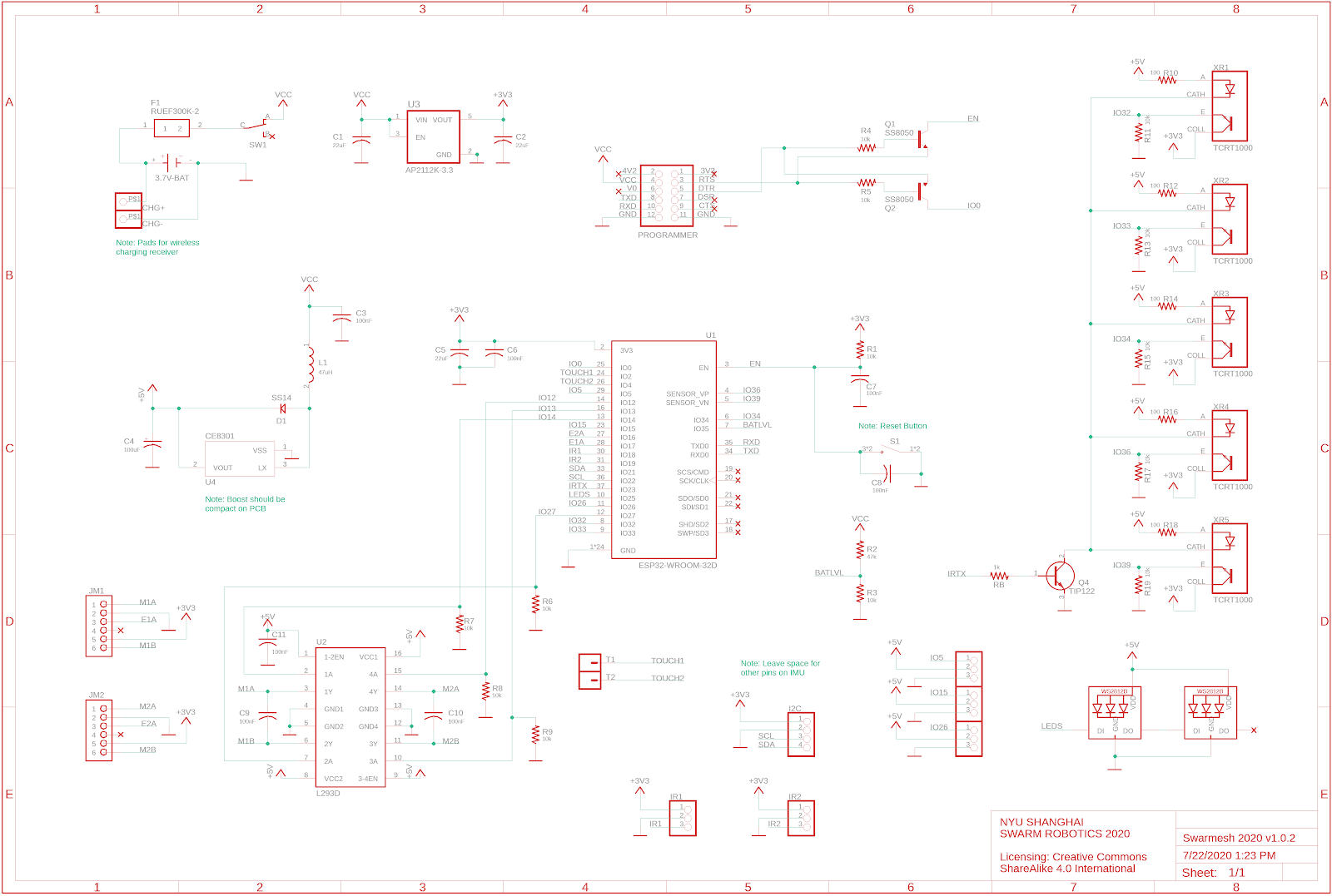
Figure 1. Schematic v1.0.2

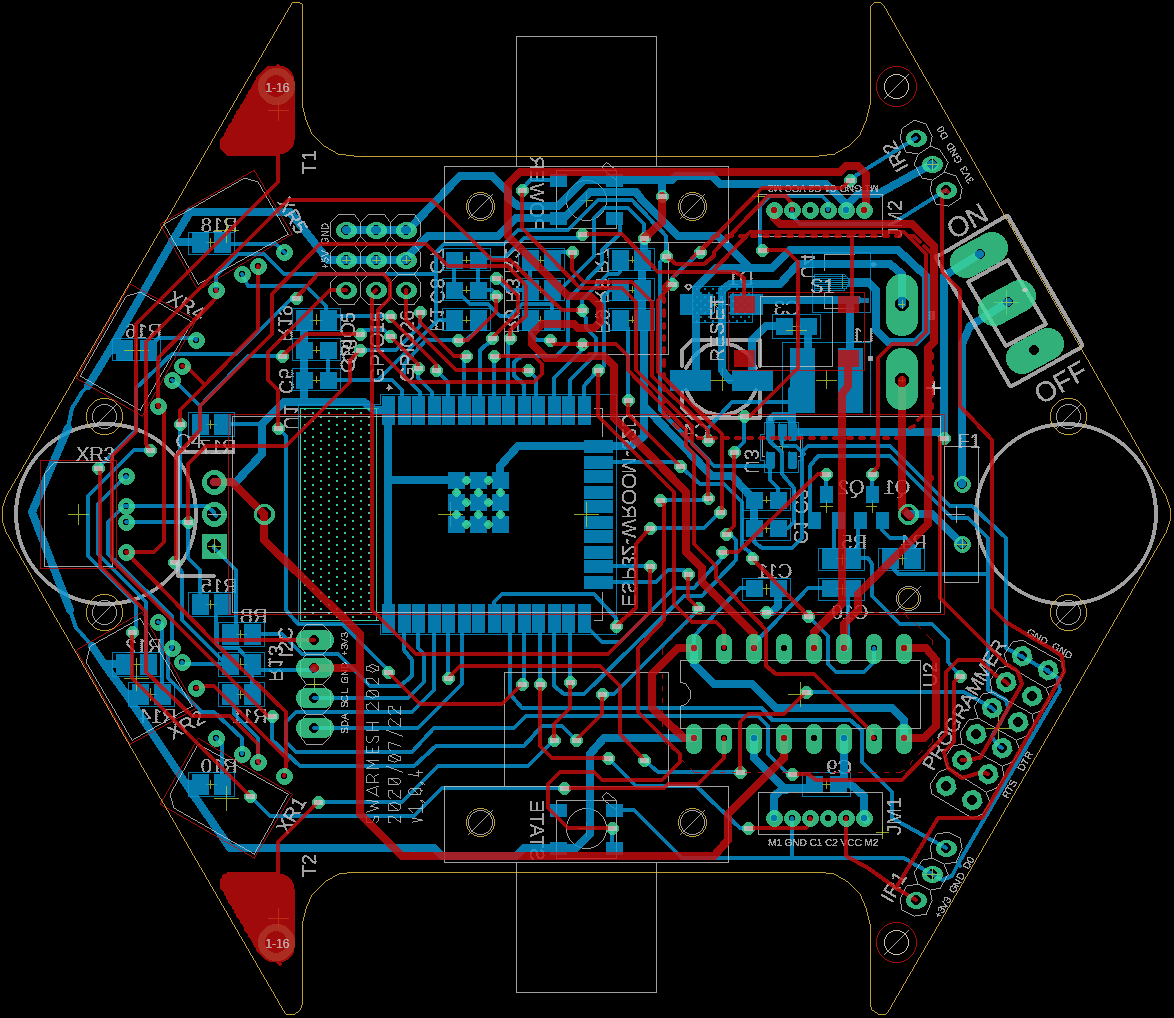
Figure 2. Board Layout v1.0.2
We ran some tests on how long the robot can run with a fully charged battery (with WIFI, motors, LED running). The result was nearly 5 hours every time which is adequate for our robot.
We came up with an idea for the placement of the wireless charging receiver on the robot. The following (figure 3) is a 3D model of the receiver holder that will be attached to the bottom of the robot. Ideally, the receiver will be attached to the holder and as the robot moves to a flat charging spot, the battery will then be charged. Therefore, the distance between the receiver and the transmitter is important. The recommended distance is between 2mm to 8mm.
 Figure 3. Receiver plate design
Once we made all the adjustments, we sent PCB v.1.0.2 for manufacturing. Figure 4 is an image of the bottom of PCB v1.0.2. The greatest weakness in this board was the infrared sensors placed at the front of the robot. Other than this, the approximate positions of all other components remained consistent with our final design. The two rows of 6 pins on the PCB are for serial communication, and we decided to use the Ai Thinker USB TO TTL programmer (Figure 5). It was a reliable product, and as expected, we were not disappointed by its performance and consistency. The reset button also worked well (looking back, it was smart to add it). The holes for the switch came out a little too large, which caused some problems in switching on the robot, but in a later version, we fixed this problem. The location of the RGB LEDs was satisfactory.
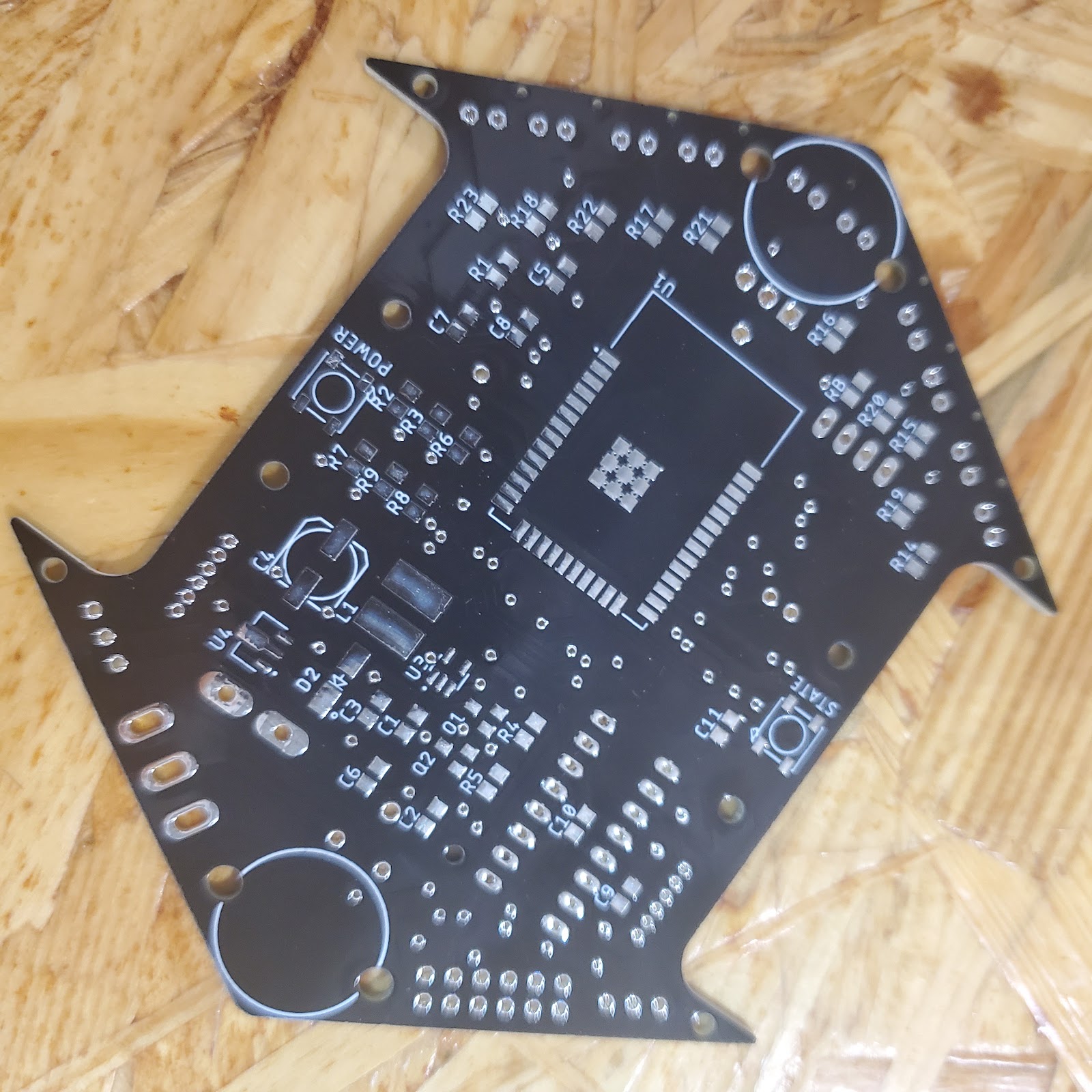 Figure 4. Bottom view of PCB v.1.0.2
 Figure 5. Ai Thinker USB TO TTL Programmer
Figure 6 is an image of the assembled v1.0.2 robot. As you can see, the infrared pairs were in an awkward position on the robot. We had placed holes in the PCB for some separators between the sensors, but it was a hassle. Hence, we spent the next week testing infrared sensors and corresponding resistor values. Due to the trouble that came with the custom separators, we decided to use infrared sensors with dividers already attached to the infrared emitter and receiver pairs. As such, we used ST188 sensors, but (take note) they are not the original sizes; instead, they were 8.7mmx5.9mm, slightly smaller than the official ones.

Figure 6. Assembled v1.0.2 Robot
The resistor values for the infrared emitters were a headache for us. The 10k ohms for the infrared receivers were fine, and we didn’t change them. We set up our apparatus on a breadboard with the esp32 dev kit, five ST188 infrared sensors, and a TIP122. After changing in resistors with varying resistances, we agreed on using the 10-ohm resistors for the emitters as the proximity for detection was huge (this was the decision that caused a big problem for us later).
Before submitting our design (v1.0.3) to the manufacturer, we added an infrared emitter on the back of the robot (LTE-302) in hopes of helping other robots know when there is a robot in front of them. This addition became another one of our mistakes as we were too hasty when adding this on.
Lastly, we added three GPIO pins with +5V and GND in order for the possible addition of servos or LED matrices. We ordered five of PCB v1.0.3 for testing.
Before moving onto the discussion of the next version, there are some status updates on the wireless charging system. There was some confusion surrounding whether the wireless charging receiver can directly charge a battery, and after talking with the manufacturers, it turned out that they cannot. We were recommended to use a TP4056 module, which is a 3.7V battery charger. We had to have a battery management system to use with the wireless charging system. Since we had a TP4056 module on hand, we soldered the cables, and consequently, the wireless charging system worked great. The problem where the charging light kept flashing after two or so hours of charging was fixed. However, this also was a letdown for us to find out so late since this addition would mean the addition of two cables. Our aim from the beginning was to minimize the number of wires.
 Figure 7. Schematic for PCB v1.0.3
As previously mentioned, the resistor values for the infrared sensors were not very friendly. Once we assembled the robot and programmed the infrared emitters to pulse in short time intervals, the infrared sensors ended up not working. Two issues caused this problem. The first was that the resistances were too small. This mistake resulted in the breakage of the emitters from the inside as the emitters couldn’t handle the big current. We measured a current that was as high as 1A even though the forward current of ST188 is only 500mA. After we realized this issue, we recalculated an appropriate resistance using the datasheets. Since we already had 100-ohm SMD resistors, we decided to be safe and use these. Even though they didn’t have a detection proximity as far as the 10ohm resistors, they still had a proximity of 30cm, which was adequate.
The second mistake was that although we wrote 47kR and 10kR for the resistors for the battery level pin, we missed the k when finding the correct resistors to solder onto the board.
One of these mistakes caused the boost converter to malfunction, and instead of boosting the 3.7V to 5V, we witnessed a voltage drop instead. Fortunately, after we fixed these issues, we had a working robot and were ready to make final adjustments and fine-tune the SMD pads for our final design v1.0.4.
We’ve also removed the infrared emitter on the back of the robot as we didn’t thoroughly test this emitter, and we were worried this would cause further problems. There were also some difficulties and complexities in using this in software-related developments.
A small perk of using bronze standoffs was that they could conduct electricity, and as a result, we extended the touchpads to the standoffs, designed plated holes, and these touchpads became touch poles.
We ordered 25 sets of v1.0.4, and asked for some help on assembling the robots. The robots came out nice and cute (controversial on the cute part). Figure 11 is an image taken during the assembly process.

Figure 11. Assembly of the robots
We had to place AruCo markers on our robots, and during the hardware developments, we had been testing the paper-printed markers on the previous 2019 model of the robots. We had to transfer the markers to our new robots, and for the robots to have a pleasing appearance, we came up with an idea to laser cut the AruCo markers. We laser cut one, tested it under the camera, and found out that at times, it was actually more stable than the paper AruCo markers. However, it also depended on the size of the AruCo marker and the size of the border surrounding the marker. We tested several with varying combinations of sizes. The size in figure 12 came out to have around the same detection consistency as what the paper AruCo markers had. As a result, we continued with this idea, and laser cut 20 sets, as shown in figure 12.

Figure 12. Laser Cut AruCo Markers
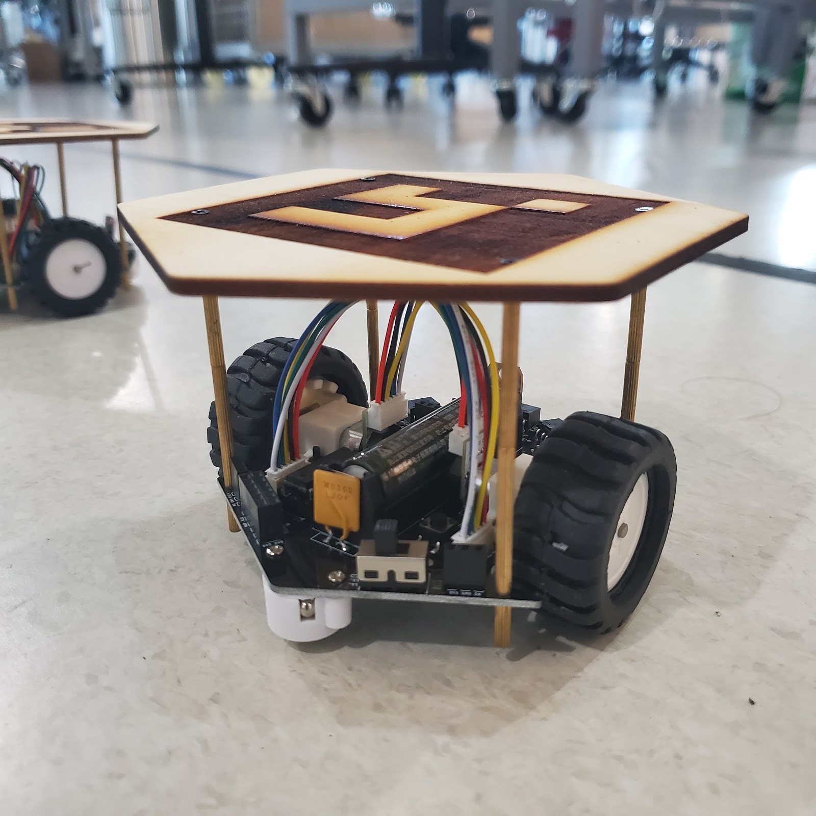
Figure 13. Robot v1.0.4 with Aurco Marker
As a backup, we also laser-cut transparent acrylic hexagons in the case we wanted to return to the paper AruCo markers. We screwed the AruCo markers onto our robots, as shown in figure 13.
After using the robots for a while, we could see further improvements to be made in maybe another version. There are two significant points.
- Wireless charging system
There was a limited time for us to complete our allotted work, and as such, we had to forgo the addition of the wireless charging system, at least for this round. We are at a stage where we can add the wireless charging system if we wanted to since they are tested and ready to go. However, it would be better if we could incorporate the TP4056 into our PCB, which would make the robot look much neater in appearance.
- Programmer and switch
There is a problem when uploading code onto the robot while the robot is switched on. It would break the esp32 and cause it to be no longer usable unless we replace certain components. Although we are not 100% sure about where the issue is, we hypothesize that it could be the combination of the 3.7V from the battery and the 5V from the USB that breaks the 3.3V LDO, which has a maximum input voltage of 6V. In another version, we should add a diode or another system to prevent this issue from happening. As of now, the robot works if we remember to switch the robot off while uploading code to it.
Discussions
Become a Hackaday.io Member
Create an account to leave a comment. Already have an account? Log In.