 piplay
Measuring Temperature
Thermocouples are thin wires of two different types. The most common are Type T which can measure a range of temperature between -270 to 370C. The unit can handle other thermocouple types for different temperature ranges. Thermocouples are connected together at one end. This end is generally referred to as the Hot Junction. The other end connects to your measurement device and is known as the cold junction. A voltage proportional to the difference between the Cold Junction and the Hot Junction temperature is generated by this temperature gradient. This voltage can be corrected and read as a temperature.
This project allows up to 16 thermocouples to be connected and their temperature read in turn. The normalisation and compensation for the ambient temperature are automatically applied and the end temperatures displayed or logged to a comma separated list in a file. Temperatures are displayed and logged in Celsius. Conversions to Fahrenheit can be done by the end user if required.
PiPlay Temperature Circuit Board
The designed circuit board consists of two Analog Devices multiplexer chips for switching between the attached thermocouples and a Maxim Precision Thermocouple to Digital converter. It also has the termination screw terminals for the attachment of the thermocouples. The board also can detect an open circuit thermocouple and flag an error to the operator.
Raspberry Pi
The project is based on a Raspberry Pi which drives the Serial Peripheral Interface (SPI) to set the Thermocouple being read and to read the temperatures. Any device capable of SPI transactions could be used if the end user prefers
Software
Software is written for the Raspberry Pi in Python which can read and display temperatures to the screen. It can also periodically log to a file in comma separated variable form. That file can then be imported to a spreadsheet and graphed if wanted.
Software is available for download in the Files area of this project. Software is in a Tarball format and a discussion on setting up your environment will be available in the Build Instructions area soon.
Screen Output
When running the screen is updated with the readings from all active thermocouples. The names provided for each channel in the .INI file will also be shown in brackets on the screen. This screen update occurs periodically as set in the variable display_interval in the .INI file.
e.g.
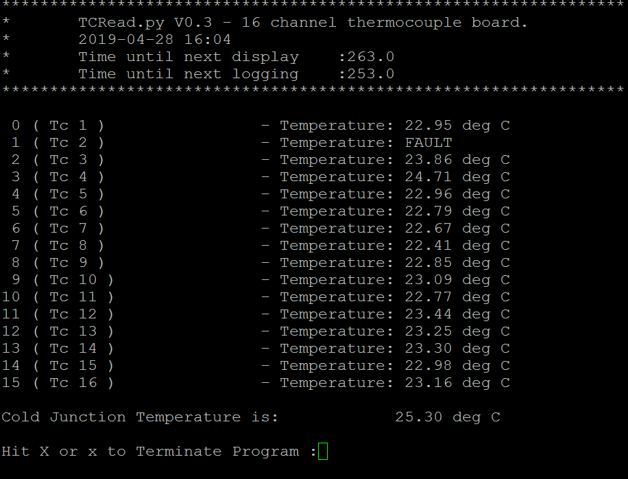
In this example one of the thermocouples is showing a Fault condition. Channel 1 with the name of Tc 1. This occurs if the thermocouple becomes open circuit or disconnected.
The outputted header shows the time and the number of seconds until the display will update and the number of seconds until the next time temperatures are logged to file. These times are set within the .INI file and a further discussion of that file is shown below.
Configuration (INI) file
Configuring the software to read Thermocouples is done in a text based configuration file. Any text editor is able to edit this file. There are a number of sections which are described below.
Default
These are the global level configuration parameters.
[Default]
# Aquisition and Logging intervals in seconds
display_interval = 300
logging_interval = 600

# Logging On/Off
logoutput = On

# Maximum Log file size in Megabytes When the maximum size is reached a new file will be created and the previous file renamed with a date/time suffix.
logfile_maximum = 1
Much of these settings are self evident. display_interval and logging_interval control how long it is between displaying to the screen and logging to a file respectively. These times are in seconds. An acquisition cycle takes approximately 10 seconds so you should not set these times more frequently. Also frequent logging can lead to self heating of the thermocouple chip and thus introduce error.
The parameter logoutput will switch on or off the logging to file. The parameter logfile_maximum will set the maximum size that the log file can become in Megabytes. Once this maximum is reached the log file will be appended with a time and date and a new file started.
Paths
# Paths used.
[Paths]
logfile = ./outputlog.csv
This section has only one parameter. The parameter logfile sets the location/path and filename of the logfile. You need to have write permission to that location. It is best to choose a .csv extension for the file to make it easier for spreadsheet programs to import and graph any resulting output.
Channel Configuration
The remainder of the ini file is configuration for each Thermocouple channel. They are basically a repeat of each parameter for each channel.
[Channel0]
status = ON
thermocouple_type = TYPE_T
name = Tc 1
The parameter status allows you to enable or disable temperature measurement for that channel. It takes the setting On or Off. Case is unimportant in the On/Off option and On oN OfF Off will all be understood. The parameters however are case sensitive. If you only have a requirement to measure 3 temperatures then you can switch the remainder of the channels off.
The parameter thermocouple_type sets the physical type of thermocouple you have connected. The syntax is very specific and is in upper case. Different thermocouple types have different temperature ranges over which they can operate. The most common are TYPE_K and TYPE_T
The last parameter in each block is name. This is a text string that describes each thermocouple and is displayed to screen and logged as the header to the log file. So instead of TC1 TC2 etc you can have real world names such as:
- Freezer 1
- Ambient Outside
- Aircon Duct 3 etc.
Uncertainty
Attached is an analysis of the uncertainty performance of the design performed by wisedesigns. It shows the raw data read by two of the units and how the errors of each unit were corrected to achieve some very impressive results in the end.
Thanks wisedesigns.
A new version fixing a mix of Tabs and spaces in indentation. Python 3 is more particular on indentation.