 Bud Bennett
Assembly:
I was careful to solder all of the surface mounted parts except the REF5025, which I hand soldered to the PCB using only the 5 pins that were connected to the circuit. I made sure to remove all of the flux with alcohol and a toothbrush. The through-hole parts were then hand soldered and the flux cleaned up as well. The LT1021 references were inserted into gold plated sockets. When power was applied all of the circuitry functioned as designed at first glance.
Two Problems:
I spent a couple of days chasing down bad assumptions.
The 2.5V Reference:
The TI REF5025 reference datasheet calls out the following circuit for the trim, which I copied without question:
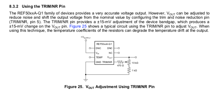
When I first applied power to the board the two LTC1021 references measured within a few mV of the target value. The REF5025 was sitting at about 3.5V. My first thought was that I had a defective IC. I was able to trim the part in the range of 2.5V, but the trim was twitchy and even small tweaks to the trim pot generated several mV of change to the 2.5V output.
I Googled "REF5025 trim error" and the search brought forth many references to the data sheet -- even a data sheet with a Burr-Brown logo, which must have been published back in the last millennium. Nobody was complaining about the trim circuit.
I then removed the 470Ω ressitor from the circuit and measured the untrimmed output voltage -- which was within a couple mV of the correct value. I also measured the resistance of the TRIM/NR pid to GND with the circuit unpowered: 1MegΩ!
So now I'm thinking that there is some serious error in the data sheet and that the 470Ω resistor should be in the range of 470kΩ instead. So I soldered a 470kΩ resistor to replace the 470Ω and viola! (I used to play the viola) the trim became much more manageable. I could now trim the 2.5V output to less than a 50µV error.
The Heater:
The entire heater/reference system was supposed to be assembled into a small box with insulating foam to isolate the PCBs from the ambient temperature. When I tested the heater circuitry I used an open cell foam which probably does not have a very good R-factor. I used a styrofoam packing material when I assembled the two PCBs into the 100x68x50mm plastic box that I intended to use for this fixture.
The component values that worked for the bench testing did not work for the new box configuration. The improved insulation and enclosed box allowed for much lower power dissipation in the heater to reach the same temperature for the set point.
The first cycle with the breadboard component values required about two hours to settle to the set point temperature, but the step response indicated that the system was pretty stable with a phase margin of better than 45 degrees. But 2 hours is too long, so I replaced the resistor, R59, that was setting the integrator time constant with a smaller value, 100kΩ instead of 680kΩ, to decrease the overall time to settle. The result was a shorter settling time, but less phase margin (maybe less than 25 degrees). This is what the response to a perturbation looks like:

Pretty ringy-dingy, but it still settles to the correct set point in about 30 minutes. This data is produced by the Keysight 34461A DMM, which doesn't attach a timestamp to the data -- go figure -- I had to assume a sample rate for the above plot to get the time information for the x-axis. If this was a design meant to be for production I would never go for this, but for a one-off it might just work. It's pretty clear that my attempt to model the physical and electrical system was way off, but it's not worth the time to figure it out for just one instance.
OTJ Learning:
I trimmed the references to the target values, at room temperature (about 12°C in my shop), and then enclosed the heater/reference PCBs within the box. I let it settle for about 1 hour and took some measurements.

The high voltage references were spot on after trimming, but the 100mV reference was too high -- measuring 100.013mV -- 0.013%. I was expecting it to be less than 0.005%. In addition, the 1V reference was a bit high as well, measuring 1.00013V, which was above my target range. Both of these reference voltages were derived from resistor dividers.
I removed the top cover and proceeded to probe various nodes in the circuit to get an idea of what could be wrong. My initial suspicion was that there was a voltage drop caused by the PCB trace resistance. I measured a few voltages between various nodes across the PCB -- I found that there was about 50µV of offset due to thermocouple effects between one node or another with just a copper wire length and two solder joints between the two nodes. With that large of thermocouple error it seemed hopeless to expect the measurement error of a 100mV source to be less than ±10µV. But the thermocouple errors should cancel if the temperature differences are small. But then I learned that there was a "Null" button on the 34461A DMM. If you are measuring µV signals then the Null button is your friend.
Enlightenment:
While I was probing the PCB to try to determine what the problems might be I noticed that the temperature of the REF5025 IC was pretty close to the set point temperature. Apparently, the heater and reference PCBs are close enough that the heater can manage the temperature of the reference board even without a cover applied. The power requirements will be higher, but it was doable.
So I just trimmed the references (with the Null feature subtracting the µV errror, as if they were in the box and regulated to the set point temperature. After I closed the box and screwed the lid down I let it soak for about 30 minutes. And then took the following readings (DMM settings: 100PLC, AZ on, High Z):
100.0057mV (0.0057% error) (nulled) 100mV range
1.000005V (0.0005% error) 1V range
2.49989V (-0.0044% error) 10V range
4.99913V (0.0174% error) 10V range (trimmed to produce accurate 1V reference)
10.0006V (0.006% error) 10 V range
These readings are well within the specification tolerances of the 34461A DMM. I'm going to let it run for about 1000 hrs (~6 weeks) and see what kind of aging drift shows up.
Discussions
Become a Hackaday.io Member
Create an account to leave a comment. Already have an account? Log In.
well done, as usuall. A few years ago, I also had the trimming problem on the reference. The 470 Ohm seemed weird and out of place in that circuit, so without much thought I assumed that the “k” was dropped by the writer and nobody noticed this.
Are you sure? yes | no