 Bud Bennett
Well, in my humble opinion, the LT1021C-10 is the clear winner. The LT1021-5 is not nearly as good, as it uses external components for temperature compensation. Neither is the REF5025A. I'm starting over with an objective to produce better stability for fewer reference voltages -- 10V, 1V, 0.1V -- all derived from a single 10V reference. Here's the schematic:
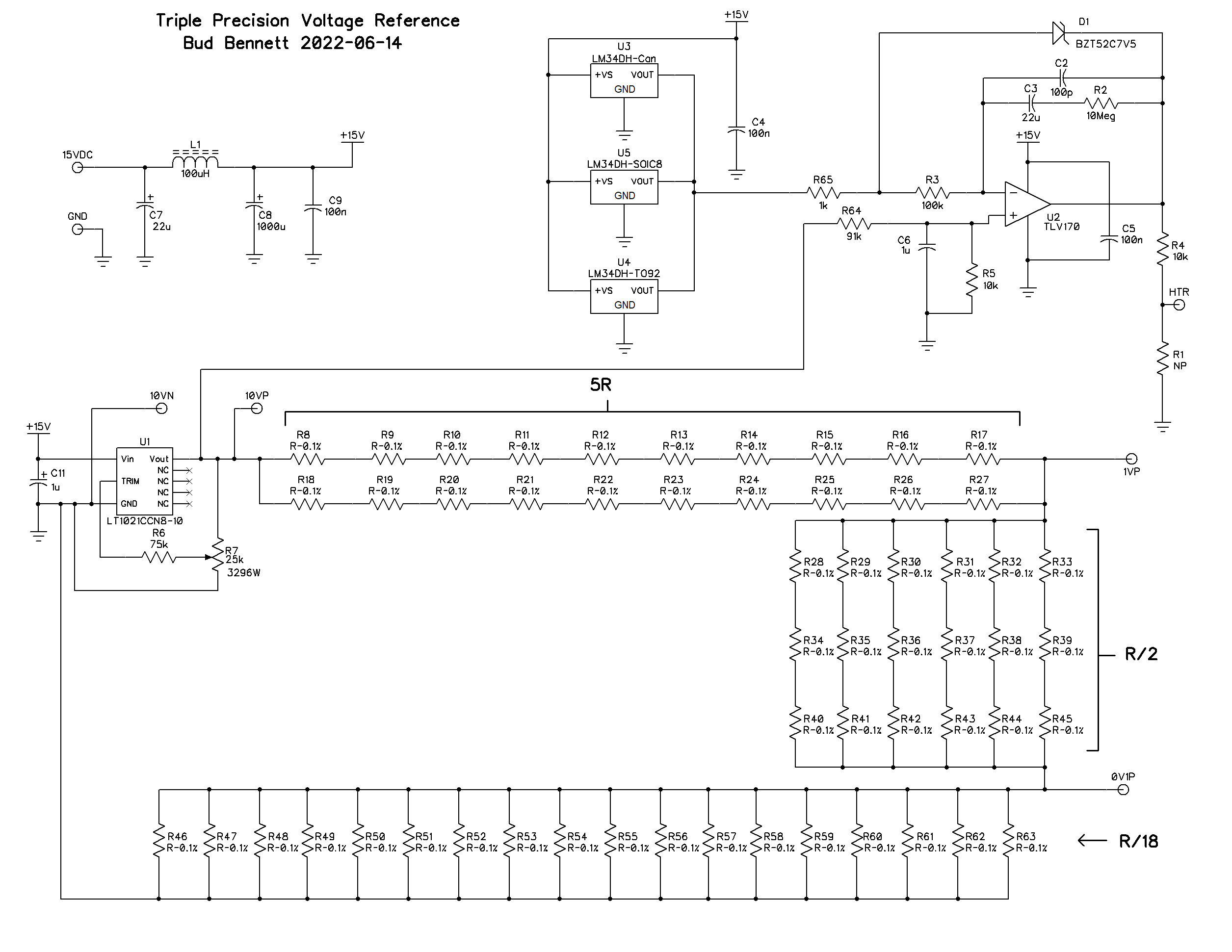
There is a single trimmer pot to adjust the LT1021 to 10V+/-100uV.
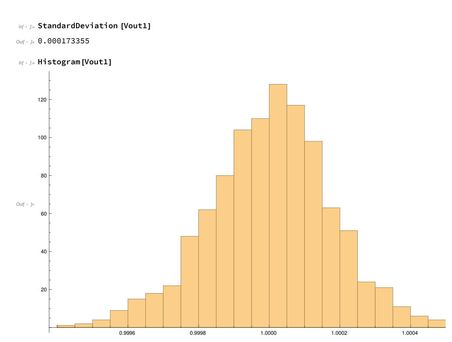
A single resistor divider produces both the 1V and 0.1V. With standard deviations of 0.0016%. There are enough of the 20k 0.1% 0805 resistors left over from my original purchase to populate the PCB. (And you can still get them, as of 2022-06-15, on eBay for a reasonable price.) But any reasonable 0805 resistor value with the same tolerance should work.
I ran a Monte Carlo simulation over 1000 cases (assuming that the 10V reference varied uniformly between +/- 100uV) , which produced this histogram for the 1V reference:
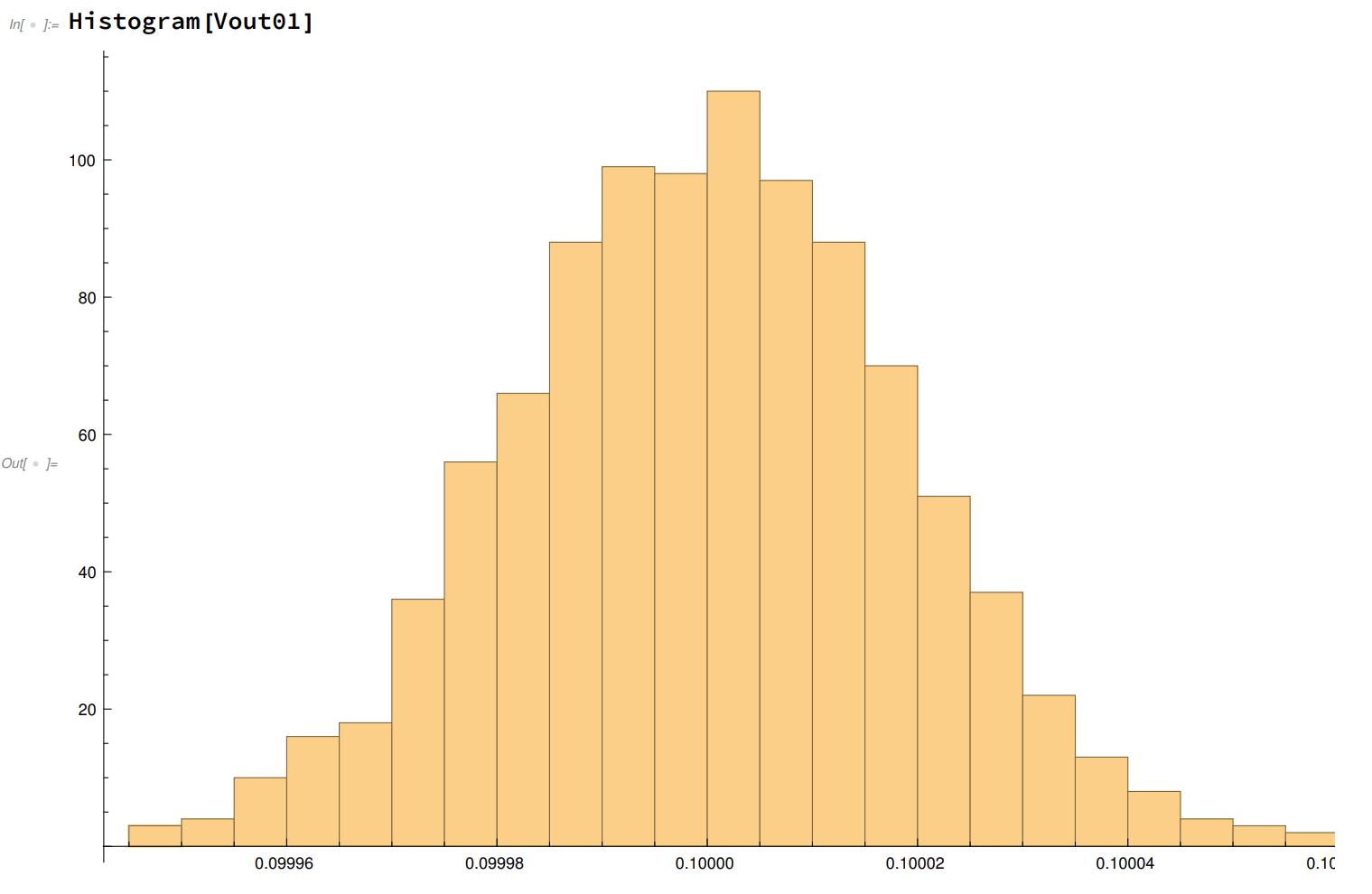
and this histogram for the 0.1V reference point:
Since the REF5025 is no longer providing a temperature output the LM34D is used instead. I have a few of these (accumulated during the 1980's most probably) in metal cans. The voltage output of the LM34D is the temperature in degrees Fahrenheit x 10mV, with an accuracy of +/- 3F. So for 100F the output would be 1.0V. No trimmer required. The LM35, providing output voltage in degrees C, could probably be used as well. These metal cans are prohibitively expensive, so I have provided for the other two possible package types (TO92 and SOIC8) to be mounted on the PCB as well -- they are less than $4/each from Digikey at the time of this log.
I added D1 to clamp the output of the PID opamp rather than let it be overdriven against either the supply or GND. This should improve the response time of the heater (I think).
The Layout:
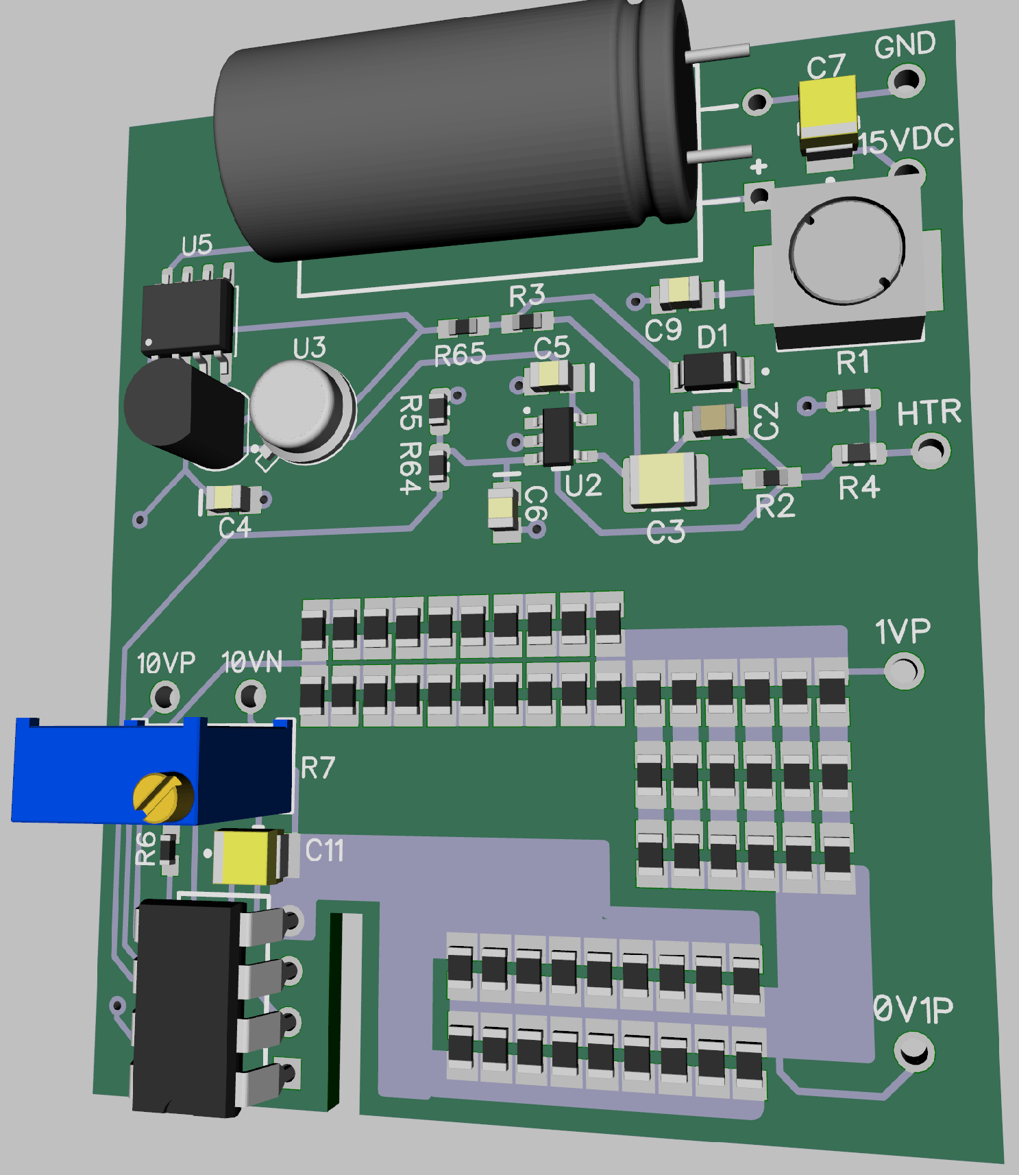
The upper half is devoted to the input filtering and the heater PID controller. The lower half is the voltage reference and divider. Note that there is only one negative reference point for all of the outputs -- 10VN. All sensitive connections are Kelvin connected, as before.
This reference box should not cost me very much. I'll be scavenging parts from the AliExpress box and don't need to purchase anything new, except the 7.5V Zener diode, which is pretty cheap.
Ordered the PCB from JLCPCB with super slow shipping.
Discussions
Become a Hackaday.io Member
Create an account to leave a comment. Already have an account? Log In.