 Shlok Jhawar
Architecture and components
PDMSS's constituents are a rover and a UAV. Here, I've explained both of them in detail.
The rover
![]()
- Block diagram:
![]()
- 3-phase code execution sequence (rover):
![]()
- Main Components
- •myRIO-1900 – The main board which controls the rover. It is a powerful multifunctional board.having an RT processor with a 40 MHz FPGA which helps in fast and precise response.
- •Wi-Fi router – for wireless communication
•An Arduinor for decoding the BMP180 & gas sensor data
•6 DC (12V) Motors – for the movement of the robot
•3 L298 modules – For running the motors
•6DOF Robotic Arm – For picking up anything the user wants to in the robot’s way
•MG996R servo motors – For use in the robotic arm
- Sensors involved
- •HC-SR04 Ultrasonic ranging sensor – helps the rover avoid obstacles.
•BMP180 Barometric Pressure and Temperature Sensor – gets temperature & altitude
•NEO-6M GPS – This is one of the most important modules on the robot. Data obtained from the GPS is transferred to the myRIO, where it is parsed.
•A camera-to get a first-person view.
•Gas sensors (MQ-7, MQ-135) – To help sense gases and air quality.
- •HC-SR04 Ultrasonic ranging sensor – helps the rover avoid obstacles.
- Physical object sampling
- Objects that the rover can come across may be vital for further analysis. For this, there is a 6DOF robotic arm.
- Power supply
- The rover is powered by a 1800mAh, 3s (3-cell) (11.1v-12.6v), 75C lithium-polymer battery.
- The LiPo battery's C rating of 75 means the battery can deliver 1.8*75=135 amps of current. Though much more than needed, it was the aptest choice due to other factors.
- I have programmed the rover using NI LabVIEW. Source files (opening "PDMS robot code.lvproj" with the environment shows the project structure)
- Chassis structure- The chassis is a two-layered combination of plywood (to ensure no bending) and polycarbonate (to provide durability, around 250 times stronger than untempered glass).
- Sensors involved


The UAV
![]()
- Block diagram:
![]() Main Components
Main Components- Flight controller (FC) (PX4) - The main board of the drone. It has an accelerometer, gyroscope, and an internal magnetometer and is used with a GPS and external magnetometer, making it an 11DOF board.
- 30A ESCs - These small boards run and control the speed of the brushless motors. Connected directly to the power supply and FC for signal, they can run a motor requiring up to 30 amperes of current.
- 2212-size 920kv brushless motors - These motors help propel the UAV upwards, providing up to 6 kgs of thrust in total. They have a maximum RPM of 14720.
- 2.4GHz radio transmitter bound to its receiver (2.4GHz) - For live control with the sticks.
- 433MHz Telemetry (100mW) - It helps in communication with the ground station, which is important when the UAV is in the air.
- 9443 size propellers.
- All this is seated on an F550 (550mm across) hexacopter frame.
- Power supply - A 5000mAh, 4s (4-cell) (14.8-16.8v) 45C Lithium-polymer battery.


All components are soldered with 63/37 or 60/40 solder.
Initialization sequence instructions
Hand drawn diagrams:
Tests & results
The data logged by the rover includes data from sensors like:
- Air quality sensor
- Temperature sensor
- Compass
- GPS
- Ultrasound
- Accelerometer
- Barometer
- PIR (for living being detection)
and a few more, with a camera.
The UAV has a camera on board (along with an 11DOF Flight controller) that gives a birds-eye view from high altitudes.
Test at field
Once everything was done, both the rover and the drone were tested outdoors.
Rover
Running the rover first, everything worked the way it was expected to. The GPS' coordinates changed with every movement over ~2 meters. I was able to get a clear first-person view from the camera on board (although there was intermittent lag sometimes when the rover was far)....
Read more »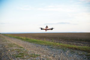
 Radu Motisan
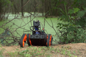
 deepankar
 J Groff
 Bash Sarbora