Close
0%
0%

SPINEO Adapter Board

A simple adapter board that lets you drive WS2812 LED's (Neopixels) using a SPI bus. Design Credit to Ben Heck.

Public Chat
Similar projects worth following
This is a simple project that only uses through hole components to drive WS2812 (Neopixel) LED's from an SPI bus. Circuit designed by Ben Heck [HaD Article: https://hackaday.com/2019/02/18/inefficient-neopixel-control-solved-with-hardware-hackery/] with universal logic replacement to reduce chip count. In reality, many people have pointed out in the comments of that article that this solution is really awful and couldn't be mass produced. I undertook it as a learning project, because I want to learn more about this sort of low-level stuff with oscilloscopes and analog techniques than just more bitbanging with micros. I want you to know that you should not try to replicate this build. There are far better ways to drive Neopixel rope, not least of which being the boards that Ben Heckendorn shows off in his SMD soldering follo

Alright well I think it's working as well as it ever will. I don't necessarily need to go into all the details on the theory of this project, as Ben Heck covers it pretty well in his video. But I am happy to share what I learned:

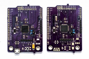
1) the .030" default drill size used for the default pin headers footprints in KiCAD is just a bit to small (at least on boards made by OSHPark). All my other components were fine but my pin headers could have been .035, maybe bigger even.

2) You need to double check the keep out zones on your footprints per IC. One of my IC's was only as long as the pins, but another stuck out about 15 or 20 mills.  It's a miracle that my pots still fit.

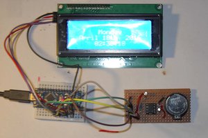
3) I think I know why my setup is having weird issues with flashing and off colors. On the WS2812 datasheet, it specified timing tolerances for high time and low time for both the 0 and 1 pulse. So it listed four times, each with a tolerance of ±150 nanoseconds. I took this to mean that it could run at a frequency of between 625 kHz and 1.17 MHz, but the datasheet also specifies on 800 kHz data transmission frequency. Oddly enough, it specifies the nominal 0 code as taking 1150 ns but the nominal 1 code taking 1300 ns. But I think that because I am not transmitting very close to 800kHz, the end of my transmission is being skewed slightly. I will probably try and design a V2 of the board, with its own onboard clock, and see if that fixes these issues. 

sketch_apr16a.ino

Arduino program that sends 3 bytes through SPI.

ino - 353.00 bytes - 04/24/2019 at 14:17

Download

  • OSHPark board arrived, strange flashes ensue

    John05/19/2019 at 11:31 0 comments

    So my shiny purple and gold OSHPark PCB's have arrived, and one of them has been populated, the picture of which should find its way into the gallery. Noteworthy developments between building the proto circuit and the PCB's arriving:

    -burnt out 2 arduino uno's trying to run the neopixel rope off an ATX power supply

    -burnt aforementioned power supply somehow

    -ordered new atmega328 DIP IC's 

    -discovered that aforementioned IC's were not bootloaded

    -ordered USB AVR programmer from Pololu

    -dicked around with programmer for some dozen hours. nothing works.

    -broke down, borrowed friends uno to as arduino ISP. Still not working

    -pulled out hair

    for context, I had two Arduino Uno's that both claimed to be R3's and to my knowledge were both genuine. However, they were two different shades of blue, had two completely different silk screens, and as it turns out, one of them was broken? I had been trying to program bootloaders onto these IC's by loading them into the board, wiring up the ICSP headers, and programming. After multiple failed attempts, I switched to the other board just for shits and giggles, and it suddenly worked. I have no idea why, as the two should be identical circuits, unless whatever fried my original IC's caused the onboard atmega16u2 on just one board to fail in such a way that it interfered with the ICSP wiring. I think this is fairly likely, as the verified functional bootloaded IC on the good board worked fine, but could still not be programmed over USB when placed in the 'bad' board. Anyways...

    I now have the v1 board soldered to an Uno and presumable transmitting good data, although I am having some weird issues. If you look at the updated code, every time the uno resets, it looks at three values in EEPROM which are used for the RGB of the whole rope. It SPI's three 0's (using a clock speed of 1MHz, the closest it can get to 800 kHz, but still within spec) then increments each color value if it doesn't already match the EEPROM value, waits 25 mS, then send out the new color data. Once the final color bytes have been written, it shuts down the SPI situation, starts a serial connection, and waits for three new color values to commit to EEPROM.

    Now the weird stuff:

    If I, for example, write 255 0 0 to my uno, then reset, during the fade in I get some weird flashes of blue and sometimes green on sections of the LED rope. The flashes seem consistent. The final color of the rope is always correct, except for one time, which I haven't reproduced so may have been a 1 time glitch.

    Secondly, if I write 0 0 0 or 1 1 1 to EEPROM, reset the board, the last ~25 or so LED's don't change. This can be fixed, if I write more than numpixels x 3 bytes of 0's to the SPI bus. This issue does not happen if I write 2 2 2 or greater. 

View project log

Enjoy this project?

Share

Discussions

Similar Projects

Does this project spark your interest?

Become a member to follow this project and never miss any updates