 Matej Nogić
Difference between other POV devices on market
One of the most important characteristics is that the displayed graphics doesn’t depend on rotation velocity thanks to its innovative solution for keeping the track of rotation angle. Meaning that the displayed graphic is perceived the same at both, higher and lower rotational speeds (for instance, when the fidget spinner is slowing down when held in the hand).
This is also one of the main difference between various POV device on the market (POV clocks, etc.) which must have a constant rotational speed in order for the image to be displayed correctly.
It is also worth noting that all the components are selected to have the lowest possible energy use in an effort to prolong the battery life


Technical Description

It uses enhanced Microchip PIC 16F1619 microcontroller as its core. The MCU has built-in Angular Timer peripheral which uses omnipolar Hall sensor DRV5033 and one magnet to keep the track of current rotational angle.
The graphics is displayed using a total of 32 LEDs, 16 green and 16 red light emitting diodes (nominal current 2mA). The diodes are driven by two 16 channel constant current shift register drivers TLC59282 connected in daisy chain.
In order to have a remote access to the device, there is a Bluetooth Low Energy module RN4871 which communicates to the microcontroller via UART interface. The device can be accessed from either a personal computer or a smartphone.
The device is turned on by using a capacitive touch button which is embedded under the solder mask on the printed circuit board. The output from the capacitive IC PCF8883 is fed to the OR logic gate BU4S71G2. The other input to the OR gates is a signal from the MCU. The output from OR gates is connected to the Enable pin of a step-down converter TPS62745. By using this setup I am able to power on/off the device by using only one touch button.
Capacitive button can also be used to change between different modes of operation or for instance to turn on the bluetooth radio only when needed in order to save energy.

Step down converter TPS62745 converts 6V nominal from the batteries to a stable 3.3V. I have choose this converter because it has high efficiency with light loads, low quiescent current, operates with a tiny 4.7uH coil, it has integrated input voltage switch which I use to measure battery's capacity with minimal current consumption and the output voltage is user-selectable by four inputs rather than feedback resistors (reduces BOM). The device goes to sleep automatically after 5min of inactivity. The current consumption in sleep is less than 7uA.

The batteries are located on the back:

Keeping the track of rotational angle
The rotational angle is tracked "by hardware“ rather by software meaning that the CPU has a lot more time at its disposal to do other tasks. For that I have used Angular Timer peripheral which is built into the used microcontroller PIC 16F1619.

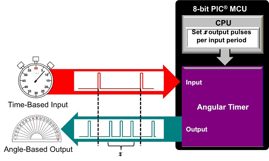
Input to the Angular Timer is a signal from Hall sensor DRV5033. The Hall sensor will generate a pulse every time a magnet passes by it. The Hall sensor is located at the spinning part of the device while the magnet is located on a static part for which the user holds the device. Since I used only one magnet that means that the Hall sensor will produce a pulse that is repeating every 360°.
At the same time Angular Timer will generate 180 pulses per revolution in which every pulse represents 2° of rotation. I choose 180 pulses, and not 360° for instance, because I found 2° to be the perfect distance between the two columns of a printed character.
The Angular Timer handles all that calculation automatically and will adjust automatically if the time between the two sensor pulses changes due to the rotation velocity changing.
The positon of the magnet and Hall sensor is shown in the picture below.

Remote Access
I wanted a way to change the displaying text dynamically and not by just hard coding it into the code. I have choose BLE because it uses a very small amount of energy and the used chip RN4871 is only 9 x 11.5 mm in dimension.
Via BT link I am able to change the displaying text and its color - red or green. I can also monitor battery level to know when it is time to replace the batteries.
The device can be controlled via computer application programmed in LabVIEW graphics programming environment or by using a freely available smartphone BLE applications which has the ability to directly write to the selected BLE Characteristics of a connected device.
For sending the information from a PC/smartphone to the device I used one Service with three Characteristics, each identified by a Handle.

PC Application

In the top-left corner we have controls for starting up the National Instruments BLE server application. That is a command line application from NI which creates a bridge between BLE module on a computer and LabVIEW. It uses HTTP protocol to communicate. The reason for using this application is that LabVIEW only has native support for Bluetooth Classic and not for BLE.
Upon successful connecting, the MAC address of a connected device is displayed on the right and that part is not grayed out anymore. There we can set the moving graphics and its color or just send some pattern to turn the LEDs on or off when the device is not spinning, I have used that for testing purposes.
Font
I generated English alphabet font using a freely available software "The Dot Factory“ but I needed to make a few modification before uploading it to the microcontroller.
The reason for that is PCB layout which is "not in order“, meaning the output 0 from LED driver is maybe not connected to the LED 0 on the PCB, OUT 1 is not connected to LED 1 but rather to LED15 for instance, and etc..
The other reason is the software only allowed to generate 2x8bit font but the device has 16 LED for each color so I needed a 16bit high font.
So I needed to make a software that would shift a few bits to compensate for PCB layout and combine them to one 16bit value.
Because of that I developed a separate application in LabVIEW that takes the font generated in "The Dot Factory“ as input and transforms it to suit the needs of this project. Since the red and green LED PCB layouts are different I needed to use two fonts. The output for the green font is shown in the picture below.

Programming jig

On the picture you can see the programming jig I have used to programe the device.
Since, after every programming, I need to pick up the device and spin it to see the changes I didn't want to use standard programming headers or just solder the programming wires.
I used Pogo pins which have a small spring inside them so they fit very tightly to the vias on the PCB.
By using this setup I am able to program the microcontroller very fast and don’t need to worry about programming wires or the left-over solder after desoldering those wires.
Conclusion
To summarize, I would like to point out that by using Angul Timer peripheral I successfully achieved a POV device which doesn’t depend on rotational velocity, so the quality of displayed graphics is kept the same at both higher and lower speeds.
By careful design I managed to implement a low energy solution which will prolong the batteries life.
As for the cons of this project I would like to point out there is no way to charge the used batteries, so battery replacement every now and then is required. No-name batteries from the local store lasted about 1 months with every-day use.
Uses:
This device can be used in a various promotional purposes or as teaching aid in electrotechnics or physics classes for instance.
It can also be used as a therapeutic aid to increase attention for those with Attention Deficit Hyperactivity Disorder (ADHD) or calm symptoms of anxiety.

3D output from Altium Designer