 Yann Guidon / YGDES
(20170118)
The character display project requires many red LEDs so I brought some.
Like, I dusted off my stock and brought whatever reference where I have a few thousands... Don't people LOVE LEDs ? :-D
I also checked my stock for 74HC595 : 120pcs (from another failed display project) is just enough for this project, niiiiiice.
But the LEDs and the driver have intricate electrical interactions that we have to prevent by testing, measuring, The 74HC595 is not a "power driver" : per the datasheets, the absolute maximum current per data output pin is 35mA, and the current must not exceed 70mA on the ground pin or the +Vcc pin.
http://www.nxp.com/documents/data_sheet/74HC_HCT595.pdf
One consequence : because of the 70mA limit, we can ensure that the board consumes at most 70×2=150mA per display. Under 5V, that's 750mW max. If you want 20 letters, get a 20 Watts power supply and you're done.
Since there are 8 outputs, each can at most supply about 70/8=8mA per pin to the respective segment. But it's a very conservative estimate.
- This can be relaxed a bit because there are 14 segments, so each 595 can drive only 7 segments. That means each segment can draw 70/7=10mA.
- Some segments have fewer LEDs so the individual LED current can be increased a bit as well. If a pair of LED draws 4mA,
- 4-LEDs segments draw 8mA
- 6-LEDs segments draw 12mA - Not all segments are energised at the same time.
- Overall current can also be increased by switching some LEDs to 0V, others to 5V. That's a naughty trick because the circuit needs a reliable potential reference and this decreases the signal integrity... Because of this, it's better to switch the "high side" to keep the ground pin "quiet" and avoid ground bounces or switching noise there.
- The 595 has internal losses, the 5V supply can also decrease due to the resistance of long wires, so the current of the LED should be calculated for a 4.5V supply.
Anyway the point is to design a text scroller, not a lighting fixture :-)
The most fun part of the day, however, is selecting which LED reference to use for the rest of the project. I've brought several types :
- Amber LED (about 4K) in PLCC2 : too hard to solder for kids
- Dark red 5mm LED (1K) : too dim
- Old (1997) 3mm flat top round LED (about 4500pcs) : OK but not as visible as the others
- SMD type (3 reels of 1500) : nice but hard to solder
- flat-top, diffused 5mm (without ring) : Good diffusion and brighter but only 1500pc available
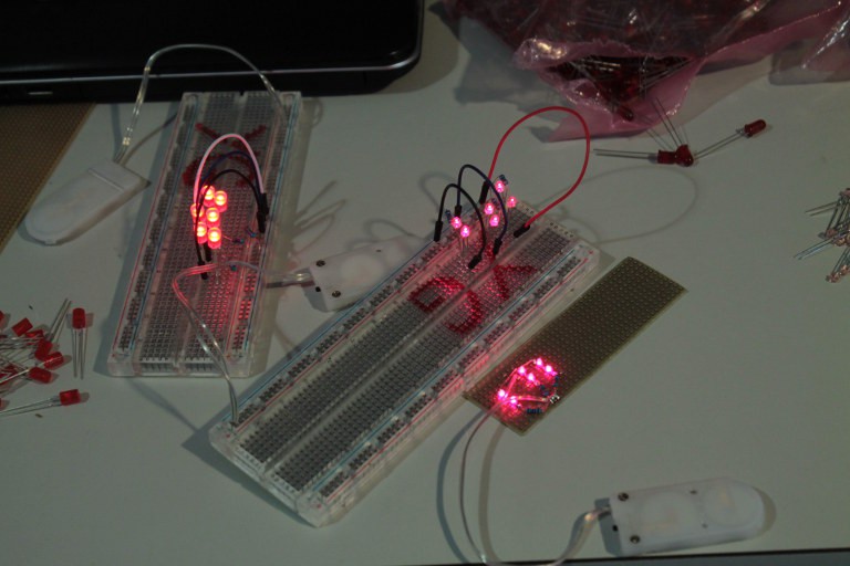
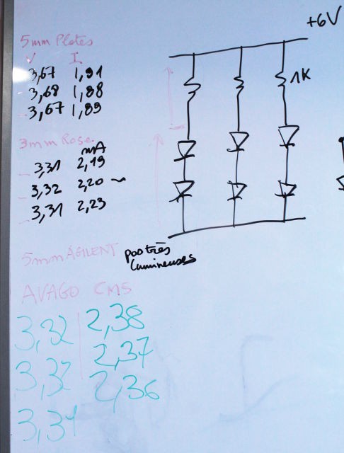
The test systems were : 3 parallel strings of 2 LEDs and one 1K resistor, powered by a Lithium battery (6V). This allows the simultaneous measurement of the current and voltage and compare the performances.
- The flat-top diffused 5mm LED have good light output but work at a higher voltage (1.85V), which could limit their use.
- The 3mm "pink" flat-top, and the Avago SMT, have a lower operating voltage (1.65V) but less diffusion, they are more "dotty". An additional diffusion layer might be required.
The jury is still out on which of these to choose.
The "flat top" is alluring but it will not be possible to make strings with 3 LEDs in series. OTOH, a string of 3 older 3mm and the Avago SMT LEDs draws about 2mA under 5V.
The LEDs are nice, but the placement matters a lot too. So we used standard predrilled prototyping boards to arrange and see how it would look in reality.
We used 5mm (collarless) LEDs because 3mm LEDs can fit but not vice versa.
The long/vertical segments use 6 LEDs, the short horizontal segments use 4 LEDs, but the pitch made it hard to fit 6 LEDs in the diagonal segments. 5 LEDs is a problematic number because it does not let us create nice pairs of LEDs.
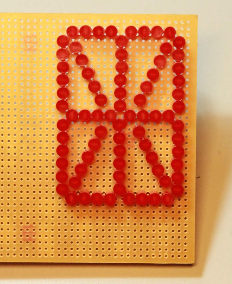
Hopefully, the final PCB will allow us to make a slightly denser diagonal with 6 LEDs because they will not be forced into a fixed grid. Pythagora's theorem says that we should ideally be able to fit 7.2 LEDs in the diagonal but there are subtle details that reduce this number.
For the first prototype, we count 80 LEDs (84 if we manage to have 6 LEDs per diagonal). That means 40 resistors, as well...
Some room must be left free for the driving circuitry (DIPswitches and shift registers).
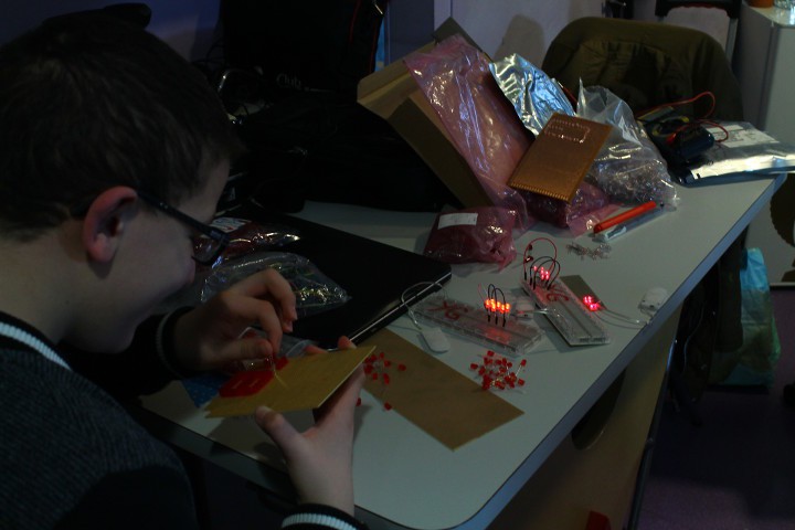
Meanwhile, Adam is already preparing a virtual mock-up with Minecraft...
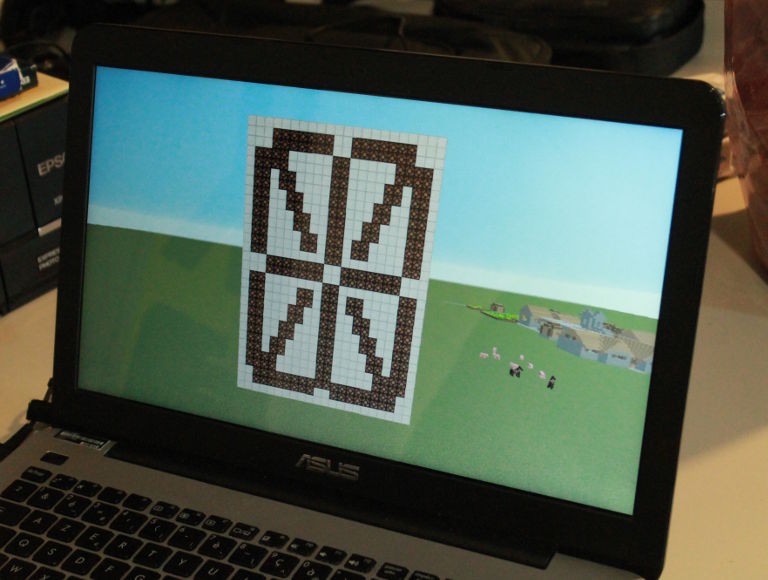
I guess it will be finished long before our material circuits :-D
About the resistors :
Reading https://www.sparkfun.com/datasheets/IC/SN74HC595.pdf I find the following data:
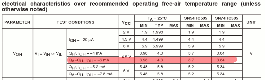
The output pins have their own significant impendance and the voltage drops near our LED's level when there is sufficient load. The drop ranges from 0.2V to 0.6V... Balancing between the strings requires some resistance, probably 50 to 100 ohms, the value is to be determined with experiments before ordering the suitable resistors.
Note for later : request a black varnish for the final PCB, to increase the contrast.
Discussions
Become a Hackaday.io Member
Create an account to leave a comment. Already have an account? Log In.