Close
0%
0%

ATtiny 0 Series programming on the cheap

The newer range of ATtinys can be programmed with an Arduino and Atmel Studio 7. NOW ALSO VIA THE ARDUINO IDE!

Similar projects worth following
Have you heard about the new ATtiny 0 (and 1) series chips? They are similar in some ways to ATtinys that went before (such as the perennial favourite ATtiny85) but with some *COOL* features. I'll do a log on some of these cool features to save space here but perhaps one feature you may be really interested in is their price. They can be very good value for the number of pins and peripherals you get!

These chips aren't programmed in the same way as e.g. ATtiny85. NOW there is ALSO an Arduino IDE core for them, but they can seem a bit daunting to try out. I was drawn in by the promised features and price, as a contender for the processor in my next revision of the #Yapolamp project.

I dug around looking for cheap hardware and free software options and eventually it dawned on me that both are available. I can't promise that this toolchain will grant you access to everything you want on the ATtiny 0 series but it will get you up and blinking and into e.g. low power

EVEN BETTER UPDATE! 17 Jul 19 - The tinyMegaCore is available to make these chips work with the Arduino IDE. We should all be grateful to Spence Konde, @Sander van de Bor and the other contributors. Go HERE: https://github.com/SpenceKonde/megaTinyCore and I will attempt to do a log on it soon.

Update - anyone interested in this project should also take a look at #ATtiny1616 break-out board for Arduino. I have a feeling these ATtiny 0 and 1 series chips will be Arduino IDE compatible before long! 

ATtiny402_PA6_blink_1s.hex

This file is the test blink programme to try uploading to the ATtiny402 to confirm "things" are working as they should (Arduino, jtag2updi, avrdude). Already compiled so you don't have to dig into Atmel Studio just to confirm the other parts of the tool chain are working.

hex - 369.00 bytes - 05/10/2019 at 08:21

Download

  • Plethora of peripherals - using interrupts, timers and events in Arduino IDE

    Simon Merrett07/23/2019 at 01:16 0 comments

    Some people who have been following #Yapolamp recently may have noticed these two projects are blurring into each other a little. Particularly this log on getting efficient pulse timing using the ATtiny402.

    This log is a bit of a handful but could serve as a helpful resource for someone who is coming to the ATtiny 0 series for the first time and has only used the Arduino IDE before.

    For context, it's worth knowing that this code is an interim program for the next version of #Yapolamp. It is a low powered torch, based on the efficient LED-driving principles of the #TritiLED project. It has two main modes, which are created in this code. 

    The first mode is an "always on" mode. It needs to pulse the LEDs at about 30Hz so that they look like they are dimly on and you could find the torch in the dark if you needed to. 30Hz is good enough so that it doesn't look like it's flashing unless you look really carefully. We need the circuit to use as little power as possible to make the supercapacitors powering it last as long as possible and to ensure it will be glowing and showing its location whenever it may be needed.

    The second mode is "fully on", which is as you would imagine, getting a decent amount of brightness out of the LEDs without wasting any of the charge in the supercapacitors.


    I'm using the ATtiny402, a chip with lots to offer for this application. The main features we're going to look at this time are its Timer Counter B0 (TCB0), its real time clock (RTC), its interrupts, events and low power STANDBY mode.

    In contrast to e.g. the ATtiny85 and older ATtinies, the new 0 and 1 series have different peripherals and you often have to use a different peripheral than you would have in the ATtiny85 to achieve the same effect. For example, to wake from sleep after a period of time with the ATtiny85, most of us would have used a WDT or watchdog timer. In the new ATtinies, that's not what a WDT is for and so it doesn't get involved in waking from sleep, only resetting if your code fails to run properly. To wake from low power modes, there are several ways we can use (great - we have choice) and they are based on the RTC.

    Timer B 

    TCB0 is similar to the timer counters you will perhaps be familiar with from the older AVRs. I haven't explored it in depth but one feature that makes it stand out for LED driving is its "single shot" mode where, based on a trigger (which I'll come back to) you can set a timer going for one single run, without repeating when it reaches the end. We can also connect this to a hardware pin and none of this depends on the cpu to execute the pulse. However, it does need a clock running so if you were to try using this in a low power mode like standby, make sure both TCB0 and the 20MHz internal oscillator are set up for standby operation (bear in mind OSC20M has something like 125uA current cost to run in standby, so you must think carefully if you want to use TCB0 in low power modes).

    Autocancelling peripherals

    Unlike the older ATtinies, it seems that the new 0 series is very good at automatically turning off peripherals, such as ADC etc, when you enter low power modes such as STANDBY. I may end up regretting that statement but I have noticed good power performance is achieved without a plethora of commands to deactivate e.g. ADC before sleeping.

    Interrupts

    Interrupts are fairly straightforward. You must take care to clear the flags from within the Interrupt Service Routine (ISR) for predictable results (I observed continuous firing without the specific interrupt conditions because I tried clearing the flag elsewhere, and I have seen other people have similar issues on the AVRfreaks forum). 

    RTC

    The RTC interrupts are worth exploring because here we have a choice. We can run the RTC overflow (OVF) interrupt to give us one ISR after a certain period and we can run the Periodic Interrupt Timer (PIT) to get a separate ISR based on the RTC's clock but at a different time than...

    Read more »

  • Reading the VCC with No GPIO! (LED debugger/UI)

    Simon Merrett05/19/2019 at 22:20 8 comments

    Intro

    There's a nifty trick you can do with some Atmel Microchip parts that allows you to read the VCC voltage without any pins other than the normal power connection; VCC - or VDD as it's referred to in the datasheets) and GND. I first heard about this on @MickMake 's demo, where he follows along with the Microchip application note AN2447

    This app note is generous enough to give sample code for the ATtiny817, which is close enough to bend for use in our ATtiny402 and many of the other 0 and 1 series parts. Note that there's a section in the app note which tells you what features your chip needs to have and therefore which chips can do this supply voltage reading trick with no extra pins or parts. BTW, the ATtiny402 isn't in that list on the current  Rev A version of the app note, so checking the ATtiny402 datasheet gave me the confidence that it had the right features to pull this off:

    •  Has an Analogue to Digital Converter - ADC
    • Allows the internally generated voltage reference (1.1V in this case) to act as an ADC input
    • Allows the VCC (or VDD) supply to be used as the ADC's reference voltage

    How it works. ADCs basically measure what fraction of an reference voltage (perhaps with a multiplier to scale it to the operating voltage of the chip) an input voltage is. These chips allow you to route the supply voltage to their ADC's reference and their internal bandgap voltage references to the ADC input to be measured. Then it's "multiplies and divides" to get a value from the ADC measurement results that represents the supply voltage.

    So the ATtiny402 is ready to read the supply voltage. But how are we going to read the ATtiny402? I have dug around a little and I don't think the D (for debugging) in UPDI is going to be available with something as low cost as jtag2updi on an Arduino Nano for a very long time, if ever. If you have the smarts to do this though, please consider this log a challenge to your abilities and show us how to do it!

    Given that we already have our ATtiny402 connected to an LED, we will use that as our user interface. We'll get it to blink the voltage to us - short blinks for whole Volts first, followed by long blinks for 1/10th Volts afterwards. Then a nice pause so we know we can stop counting!


    Method

    Firstly, you need to have got yourself to the point that you can open a project in Atmel Studio and have a way of uploading the compiled code to your ATtiny402. This could either be from the command line with avrdude or by adding your jtag2updi programmer to Atmel Studio and uploading from there. This is where we got up to in the last log.

    A refresher on the connections:

    Then we will compile and upload the following code:

    /*
     * ATtiny402VoltageMeasure.c
     * This code reads the voltage on the ATtiny Vcc supply pin (Pin 1)
     * and blinks the result. No external voltage references, 
     * voltage dividers or other pins are required.
     * Created: 16/05/2019 01:30:05
     * Author : Simon
     */ 
    
    #ifndef F_CPU
    #define F_CPU 3300000UL // 20 MHz clock speed / 6 prescaler
    #endif
    
    #include <util/delay.h>
    #include <avr/io.h>
    
    /* A custom (not library) function to delay for a variable number of milliseconds*/
    void delay_ms(int count){
        while(count--){                // check if greater than 0 and decrement the counter for next iteration 
        _delay_ms(1);                  // wait 1 millisecond
        }
    }
    
    /* A function to blink the LED, using the custom delay function*/
    void blink(int flashes, int duration){
        while(flashes--){              // check if greater than 0 and decrement the flash counter for next iteration
        PORTA.OUTSET = PIN6_bm;        // LED off
        delay_ms(duration);            // wait for a set number of milliseconds using non-library function
        PORTA.OUTCLR = PIN6_bm;        // LED on
        _delay_ms(200);                // wait for 200 milliseconds
        }
    }
    
    int main(void)
    {
    /* This first step is to ensure we have correct clock settings
     * as we may have changed the clock source, frequency or...
    Read more »

  • Open a Project in Atmel Studio, Compile and Upload Code

    Simon Merrett05/16/2019 at 00:04 1 comment

    In this log, we'll write a basic programme in Atmel Studio for the ATtiny402 which demonstrates one of its major advantages over the ATtinys and even ATMEGAs which went before: the ability to avoid the need to set fuses with a programmer.

    If this doesn't strike you as wonderful, what it means is that we don't need to wait for avrdude or Arduino IDE to work out how to talk UPDI (although I'm sure it will get done soon with the new Arduino programming interface freedoms that have recently been announced) to set things like:

    • Brownout detection
    • Watchdog settings
    • CLOCK speeds!

    Yes, that's right, we no longer need to set the clock configuration before we upload code! We can even dynamically change both the clock speed AND source from within the programme! This opens up huge opportunities, such as running from the 32kHz internal oscillator down to 18uA - no need to sleep if you want the device to always be on and ready to respond to human timescale events.

    In Atmel Studio, open a new project:

    We need to give it a name (I left everything else as defaults) and then click on the option for a GCC C Executable Project and then click OK:

    And select ATtiny402 from the parts list, before clicking OK again. It will now create and open your project.

    Atmel Studio will open your main.c file with the bare minimum structure in there and it will look similar to this:


    However, we want some more funtional code to go in there, so how about:
    /*
     * ATtiny402LowPowerRunning.c
     * These settings (F_CPU 32000UL, 0 prescaler, all GPIOs apart from LED pin set to pullup inc UPDI, force OSC20M off)
     * Result in a processor current draw of 16uA!
     * Created: 05/05/2019 20:46:56
     * Author : Simon
     */ 
    
    #ifndef F_CPU
    #define F_CPU 32000UL // 32 kHz clock speed / 0 prescaler divisor
    #endif
    
    #include <util/delay.h>	// needed for our delay
    #include <avr/io.h>
    
    int main (void)
    {
    
    	/* Set the Main clock to internal 32kHz oscillator*/
    	_PROTECTED_WRITE(CLKCTRL.MCLKCTRLA, CLKCTRL_CLKSEL_OSCULP32K_gc);
    	/* Set the Main clock prescaler divisor to 2X and disable the Main clock prescaler */
    	_PROTECTED_WRITE(CLKCTRL.MCLKCTRLB, CLKCTRL_PDIV_2X_gc); // without enable
    	/* ensure 20MHz isn't forced on*/
    	_PROTECTED_WRITE(CLKCTRL.OSC20MCTRLA, 0x00);
    
    	/* Configure Port A, Pin 6 as an output (remember to connect LED to PB6 and use a resistor in series to GND)*/
    	PORTA.DIRSET = PIN6_bm;
    	
    	/* Set all pins except the LED pin to pullups*/
    	PORTA.PIN0CTRL = PORT_PULLUPEN_bm;
    	PORTA.PIN1CTRL = PORT_PULLUPEN_bm;
    	PORTA.PIN2CTRL = PORT_PULLUPEN_bm;
    	PORTA.PIN3CTRL = PORT_PULLUPEN_bm;
    	//PORTA.PIN6CTRL = PORT_PULLUPEN_bm; // LED pin
    	PORTA.PIN7CTRL = PORT_PULLUPEN_bm;
    	
    	
    	while (1)
    	{
    		// PAUSE 1000 milliseconds
    		_delay_ms(1000);
    		
    		// LED off 
    		PORTA.OUTCLR = PIN6_bm;
    		
    		// PAUSE 2000 milliseconds
    		_delay_ms(2000);
    		
    		// LED on
    		PORTA.OUTSET = PIN6_bm;
    	}
    }

    Let's take the code section by section so that if you are more familiar with the Arduino IDE, we can give a nice introduction to Atmel Studio (but a VERY basic intro), to get you up and blinking from the source code.

    #ifndef F_CPU
    #define F_CPU 32000UL // 32 kHz clock speed / 0 prescaler divisor
    #endif

    This section is something we don't have to worry about with Arduinos usually, as their clocks are set outside the sketch. This tells the compiler what speed the microcontroller is going to run at - in this case I have rounded down to 32kHz exactly, although this isn't the real speed of the internal oscillator. Good enough for now but you may want to change. If we don't get this roughly right, all sorts of timer type items will go wrong, such as millis() being a different length than 1ms.  Bear in mind that the clock speed is made up of both an oscillator frequency (you can also use the internal 20MHz oscillator or choose to run that same oscillator at 16MHz) and a prescaler divider, such as 2, 8, 48, 64 (not exhaustive). The oscillator speed divided by the prescaler divisor is the number you want to put in this #define. PS, it's about...

    Read more »

  • Set Up Atmel Studio for ATtiny and Add jtag2updi Programmer

    Simon Merrett05/15/2019 at 23:01 5 comments

    We're going to open Atmel Studio and add our device pack for ATtiny, then add our hardware programmer to the list of devices we can use to programme from within Atmel Studio (such as the Atmel ICE programmer). This should speed up our development iterations over using avrdude from the command line each time we want to upload code to the ATtiny.

    Open up Atmel Studio and open Tools\Device Pack Manager: 

    On Windows you may be asked if you want Device Pack Manager to make changes to your system. I clicked Yes.

    If you have a green icon and an "Install" button next to ATtiny DFP 1.3.229 click it and follow the instructions so it installs and you end up looking like this:

    You can now close the Device Pack Manager and go back to the main Atmel Studio screen. Now we're going to add our jtag2updi Arduino as a hardware programmer that uses avrdude from within Atmel Studio. Click Tools\External Tools 

    And a window will pop up like this one, which you are going to copy the contents of into yours:

    • Title. Give the tool a descriptive title - note that this tool is tied to the part you're programming because of how it commands avrdude. So you need to add external tools for each part you program, as far as I know.
    • Command.
      C:\avrdude\avrdude.exe
      This, except make sure the file path is wherever you have saved avrdude.exe:
    • Arguments. The key part to get here is the target part being programmed (look in avrdude.conf for nicknames of parts) and the COM port number (6 in my case)  
      avrdude -P com6 -c jtag2updi -p t402w -U flash:w:$(ProjectDir)Debug\$(TargetName).hex:i
    • I followed a guide which didn't mention putting anything in Initial Directory and to tick Use Output window but leave unticked both Prompt for arguments and Treat output as Unicode.
    • Then click OK.

    You should be all set to programme your ATtiny402 from Atmel Studio now! I have written this guide a couple of weeks after I first went through the process so if I have missed a step, please shout in the comments.

  • Talk to the ATtiny402 with the Arduino: Establish Connection and Get Blinks

    Simon Merrett05/10/2019 at 08:24 3 comments

    Remember that for other ATtinys than the ATtiny402, this may not work in the same way. You will have to work out your own chip's VCC, GND and UPDI pins but they probably won't look too different to the setup here

    We're following the same setup as shown in the jtag2updi repository, except that V_target = V_programmer. This doesn't always have to be the case but you will need to take care about logic levels if your V_prog and V_tgt are significantly different. One microcontroller's 1 can be another's 0... ElTangas hasn't tried it with logic level converters according to the link above but while we are programming the chips at 5V and the components around them can handle 5V, we don't need to worry.

    Just for clarity on the ATtiny402:

    • Arduino GND -> ATtiny402 GND = pin 8
    • Arduino 5V    -> ATtiny402 VCC = pin 1
    • Arduino D6 -> 4.7k resistor -> ATtiny402 pin 6

    Open up a command prompt (I'm using Win10, so you will have to adapt this to another OS you may be using). If you haven't done this before, it's easily done by typing command into the Windows search/magnifying glass bar in the bottom left of the desktop, next to the Windows button:

    When you click on the Command Prompt app, it will launch into something like a white text on black background saying something like:

    Microsoft Windows [Version 10.0.17763.475]
    (c) 2018 Microsoft Corporation. All rights reserved.
    
    C:\Users\"YOUR_PROFILE_NAME">

     Where YOUR_PROFILE_NAME is the account name you use on Windows. This isn't where we installed avrdude.exe (the application file) to, so we need to go there now before we can use it. To do this, type:

    cd c:\avrdude

    (or wherever you installed avrdude to) and press enter.

    Don't forget to plug in your Arduino to a USB port and confirm which COM port it is connected to, either using the Arduino IDE or looking in Windows Device Manager. Remember this from an earlier step: 

    In my case, we were uploading to the Arduino Nano on COM 6. We'll need this now. 

    The first check we're going to do is read the device signature and check if it is locked for programming. We should find a new chip unlocked for programming and there is a troubleshooting step for locked chips at the jtag2updi repository. The avrdude programme runs on text commands from the command prompt. We type in a string of characters and it interprets these as detailed commands about what you want the programme to try and do. To try an initial communication with the chip and find out if it is locked, we type:

    avrdude -c jtag2updi -P com6 -p t402

    Where: 

    • "avrdude" starts the programme 
    • "-c jtag2updi" sets the programming interface type
    • "-P com6" is the COM port we are asking to connect to the chip over (capitals make a difference in avrdude letter commands)
    • "-p t402" means the part we are trying to talk to. In the avrdude.conf file, an ATtiny402 is given the nickname "t402" to save typing effort in the avrdude command string!

    Here's my command and this is the response I got....

    c:\avrdude>avrdude -c jtag2updi -P com6 -p t402
    
    avrdude: AVR device initialized and ready to accept instructions
    
    Reading | ################################################## | 100% 0.31s
    
    avrdude: Device signature = 0x1e9225 (probably t406)
    avrdude: Expected signature for ATtiny402 is 1E 92 27
             Double check chip, or use -F to override this check.
    
    avrdude done.  Thank you.

     Oh dear. What kind of chip have I connected? In this state, avrdude won't let me upload code because it thinks I have made a mistake and connected a different chip. Uploading code compiled for the ATtiny402 to a different chip could brick it, so avrdude is trying to protect me from bricking my attached chip. On the plus side, the Arduino Nano with jtag2updi loaded and avrdude controlling them were able to read the device signature - HOORAY!

    You may remember me prattling on about hardware bugs in a previous step - this is one of them. Some...

    Read more »

  • Programme Your Programmer

    Simon Merrett05/09/2019 at 08:29 0 comments

    This is just a quick log to walk through uploading the jtag2updi software to the Arduino so that it will act as the hardware piece of our programming tool chain, taking in jtag and spitting out updi.

    1. Make sure you have installed all the software in the previous step and open the Arduino IDE. 
    2. Open File\Sketchbook\jtag2updi:
    3. Set up the board you are programming by selecting Tools\Board = Arduino Nano and Tools\Port = whatever COM port number your Arduino is connected to:

      Note that the jtag2updi sketch has absolutely no text in it - this is deliberate and the upload should still work! Leave everything else as defaults for now.

    4. Now to upload press ctrl+u or click the upload button:

    5. If it didn't manage to upload to the Nano, try using the Tools\Processor = ATMEGA328P Old Bootloader:

    6. That's it! Other than being told in the black output console at the bottom of the Arduino IDE that the sketch has successfully been uploaded, the proof/verification that this has all worked will come in another step.

  • Software First Steps: Downloads and Basic Installs

    Simon Merrett05/08/2019 at 09:34 0 comments

    I decided this might be better as a log, which I can then reference from the instructions. This might seem like a long-winded explanation but I wanted to include details that might help people that aren't confidently doing this sort of thing frequently. Once it's set up, it is much less hassle than the explanation below may give you the impression that it is!

    In summary, we are going to use the following collection of software tools:

    • Arduino IDE (I used version 1.8.9)
    • avrdude (may be optional - I used version 6.3)
    • jtag2updi
    • Atmel Studio (I used version 7) with ATtiny Device Pack (I used version 1.3.229)

    1.  Install Arduino IDE

    Available from https://www.arduino.cc/en/Main/Software. I used the Windows installer (not the Windows App Store version) but it probably doesn't make any difference.

    2.  Install avrdude

    This tool is used for uploading files to chips and reading memory from chips too. It is installed as part of your Arduino installation but we want to amend its default configuration specially for use with the new chips and the jtag2updi tool, so we'll install a separate instance somewhere that we can customise it. It is available from http://download.savannah.gnu.org/releases/avrdude/. I used version 6.3 for windows, named:

    avrdude-6.3-mingw32.zip

    Which sits here on the webpage: 

    You may prefer to create your folder for avrdude somewhere else but for ease, I created the folder: 

    C:\avrdude\

    C:\avrdude\

    and into it, I extracted from the zip folder:

    avrdude.exe 
    avrdude.conf

     So now we have:

    We need to rename or delete avrdude.conf so that it is ignored by avrdude.exe and we will put the custom avrdude.conf file from the jtag2updi repository in the avrdude folder instead. I renamed my original avrdude.conf as:

    ORIGINALavrdude.conf

    3.  Install jtag2updi

    Available from https://github.com/ElTangas/jtag2updi. If you have never used code from github before, it's not always clear how to download it. I do run git but for this the simplest method for most people in my view is to press the "download Zip" option:

    This will download a .zip folder in your Downloads folder called: 

    jtag2updi-master.zip

    Open it and follow the instructions kindly provided by ElTangas here: https://github.com/ElTangas/jtag2updi#building-with-arduino-ide

    I extracted the contents of the Source folder in the zip folder to a new folder in the sketches folder of my Arduino installation. This would look something like:

    C:\Users\"YOUR_PROFILE"\Documents\Arduino\jtag2updi

    where "YOUR_PROFILE" is the account name that you use on a Win10 machine. These are the key elements you're looking for:

    Now go back to the jtag2updi-master.zip folder and extract the jtag2updi version of avrdude.conf to the avrdude folder you set up in step 3. It is kept here in the jtag2updi-master.zip\jtag2updi\ folder:

    your avrdude folder should now have the avrdude.exe file and the jtag2updi version of the avrdude.conf file in it, as well as any renamed ORIGINALavrdude.conf file:
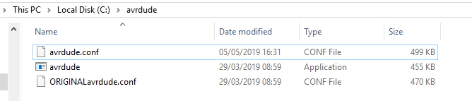
    4.  Install Atmel Studio

    Available from this link: https://www.microchip.com/mplab/avr-support/atmel-studio-7

    I used the web installer and I don't recall selecting anything other than the default options (if there are any options). 

    5.  Install ATtiny Device Pack for Atmel Studio

    This is a modular piece of software which describes the ATtiny chips, so as to keep chip definitions separate from the main software tool. It makes sense to allow bug fixes for individual chips without needing to install new versions of Atmel Studio but it's not obvious to many beginners that they ALSO need the relevant device pack installed for their chip-of-interest.

    You can get the ATtiny device pack from here: http://packs.download.atmel.com/. I used version 1.3.229 and it is to be expected that there are bugs in the early stages of hardware releases. Some of these bugs are not...

    Read more »

View all 7 project logs

  • 1
    Get your parts!

    As a bare minimum you will need 

    • an Arduino (I used a Nano) with a USB interface (cable, USB-serial adapter if not already on your Arduino)
    • an ATtiny 0 series in some connectable form. I used a SOIC to 0.1" adapter PCB on a breadboard
    • a computer. I used a Win10 machine and haven't tried it on other platforms so YMMV.
    • jumper wires/leads x3 for the connection between Arduino and ATTiny (VCC, GND and UPDI). If you are feeling fancy, you can add 2x more wires and use the common voltage rails on your breadboard.
    • a 4.7k resistor to go in series with the UPDI wire
    • OPTIONAL (but recommended) - an LED with current-limiting resistor (>220 Ohm)
  • 2
    Do initial software downloads and installations

    The details of this instruction are in this log, so as not to clog up the instructions.

  • 3
    Programme your Arduino to be the jtag2updi hardware programmer

    I popped the details of this step in this log.

View all 6 instructions

Enjoy this project?

Share

Discussions

Stephen Porter wrote 01/25/2021 at 03:21 point

Simon, thanks for putting so much care and detail into writing this tutorial. It's been extremely helpful in getting this EE off the ground with embedded programming!

  Are you sure? yes | no

Simon Merrett wrote 01/25/2021 at 08:26 point

Delighted to hear it has helped you and thank you for taking the time to let me know. 

  Are you sure? yes | no

Simon Merrett wrote 06/19/2019 at 19:26 point

Hi everyone, if you are interested in this project, you may be excited to learn about this ATtiny core for some of the new 0 and 1 series - hot off the press! 

https://github.com/SpenceKonde/megaTinyCore

  Are you sure? yes | no

Alan Green wrote 05/16/2019 at 20:01 point

I'm enjoying this series greatly, thank you.

  Are you sure? yes | no

Simon Merrett wrote 05/16/2019 at 20:22 point

@Alan Green that's great, thanks for taking the time to let me know. I have to admit that we're pretty much at the limit of my knowledge about the chips. Nevertheless, I'm sure ideas for future logs will pop up. If you want to contribute, please join in. 

I'd love to get some cheapo debugging going, purely because it's a great way to have an interface on a barebones chip. However, refactoring EDBG onto a cheap microcontroller is well beyond my current skill! 

  Are you sure? yes | no

Similar Projects

Does this project spark your interest?

Become a member to follow this project and never miss any updates