 Abel Rodriguez
-Motivation:
This project was intended to serve as a test for various technologies and softwares.
I work as a electronic engineer so I'm used to design electronics for consumer applications. But to do a project as a maker, without using too much external companies was a challenge for me.
I've made this project to learn and be accustomed to work with 3d design and printers, to make my own prototipes with the best quality, and to develop firmware for the cheapest microcontrollers with the free tools available. Also to learn how to use some machines in the makerspace I'm member (http://www.made-bcn.org/)
I've designed the circuit with Altium designer due is what I've disponible, but CircuitMaker was an option also.
I've made a database of components to be used as a library for the Altium and to generate better component lists.
The box is designed in solidworks and printed in a BQ Hephestos printer. The rear cover and the led light guide are cutted by laser.
The pcb's where made in Elecrow, but I've ordered also the stencil, made a manual stencil printer and use it to mount the components by hand, then solder the components in a T-962C SMD oven.
The front sticker is designed in Inkscape and ordered to print and cutted in vinyl.
Most of the components are from Farnell, Mouser, etc.. but the knob is directly from the manufacturer, buyed thru Alibaba. This served to test how to work with Alibaba, to realize how different is from Aliexpress and how difficult could be to talk with the manufacturer when there is a problem with the shipment.
The microcontroller was chosen to be cheap and simple, also with free tools. I usually work with cortex microcontrollers, but this 8bits microcontroller was also fun to program. The IDE is the STVD from ST, but the compiler is the CXSTM8 from http://www.cosmic-software.com
So, there is lot I've learned with this project and I hope it will serve to make other project quicker.
-Operation:
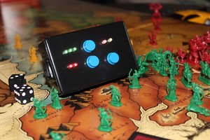
The rotative encoder is used to control all the functions of the electronics. Is used to start the microcontroller supplying power directly to it when pushed, then the microcontroller will fix on the input supply thru the load switch TPS22929.
There are 5 modes of operation that could be changed pushing the encoder. The current mode are showed with the 5 leds over the 7 segment display. The three first ones are lifecounters and they start at 20 by default, you could change up to 999 and down to -99. The fourth mode is a timer that is set to 1:00 by default, can be changed up to 45min. Due the 3 digit limit, when showing times over 10 min, only the minutes and the high digit of the seconds will be show, 35:40 will be shown as 35.4. Under 10 minutes will be shown normally. When the time is up the buzzer will fire three times. if you push the button then the timer will recover its first set value.
To start and stop the timer the push button function must be used, so to change the mode to the next one the button must be pusshed 2 seconds and the display will show 'out', and releasing the button will change to the next mode. If the timer is on when going to another mode, the decimal point pf the rightest digit will blink each second to show that the timer is still running.
The fourth mode is the dice, when selecting this mode a 'd6' will be showed in the display, with the encoder you could select these dices: d4, 2d4, d6, 2d6, d8, 2d8, d10, d12, d20, d30 and d100. After selec the dice, the push button will throw a random of the value selected. If it's a 2dx dice then will throw it 2 times and add the results.
To change the mode also the push button must be pushed 2 seconds and 'out' will be showed. In any mode, to power off the circuit push the button 3seconds and 'off' will be showed, then when releasing the button the load switch will be set off and the the power supply will be disconnected from the batteries.
 Scott Clandinin
 sjm4306
 Maso
Maso
 Doubleyou