Thanks to a YouTube video from the Chaos Computer Club I learned that colophony can be used to decap integrated circuits. Decapping is shorthand for "de-encapsulating," meaning removing a silicon die from its packaging. Decapping usually involves concentrated sulfuric acid or even fuming nitric acid, both of which are expensive and dangerous chemicals that are difficult for the average person to get a hold of (especially fuming nitric).
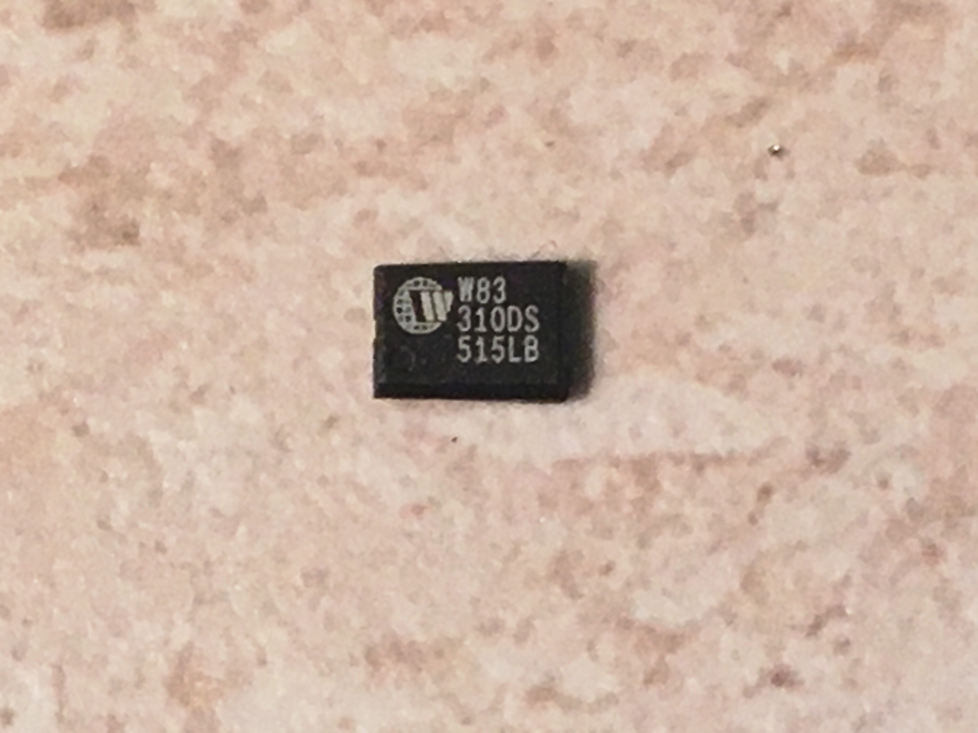
Colophony however is another name for rosin, the same stuff used to make soldering flux, and is safe enough to hold in your hand. This revelation started this project to find ways of decapping ICs using inexpensive and widely available tools and chemicals.
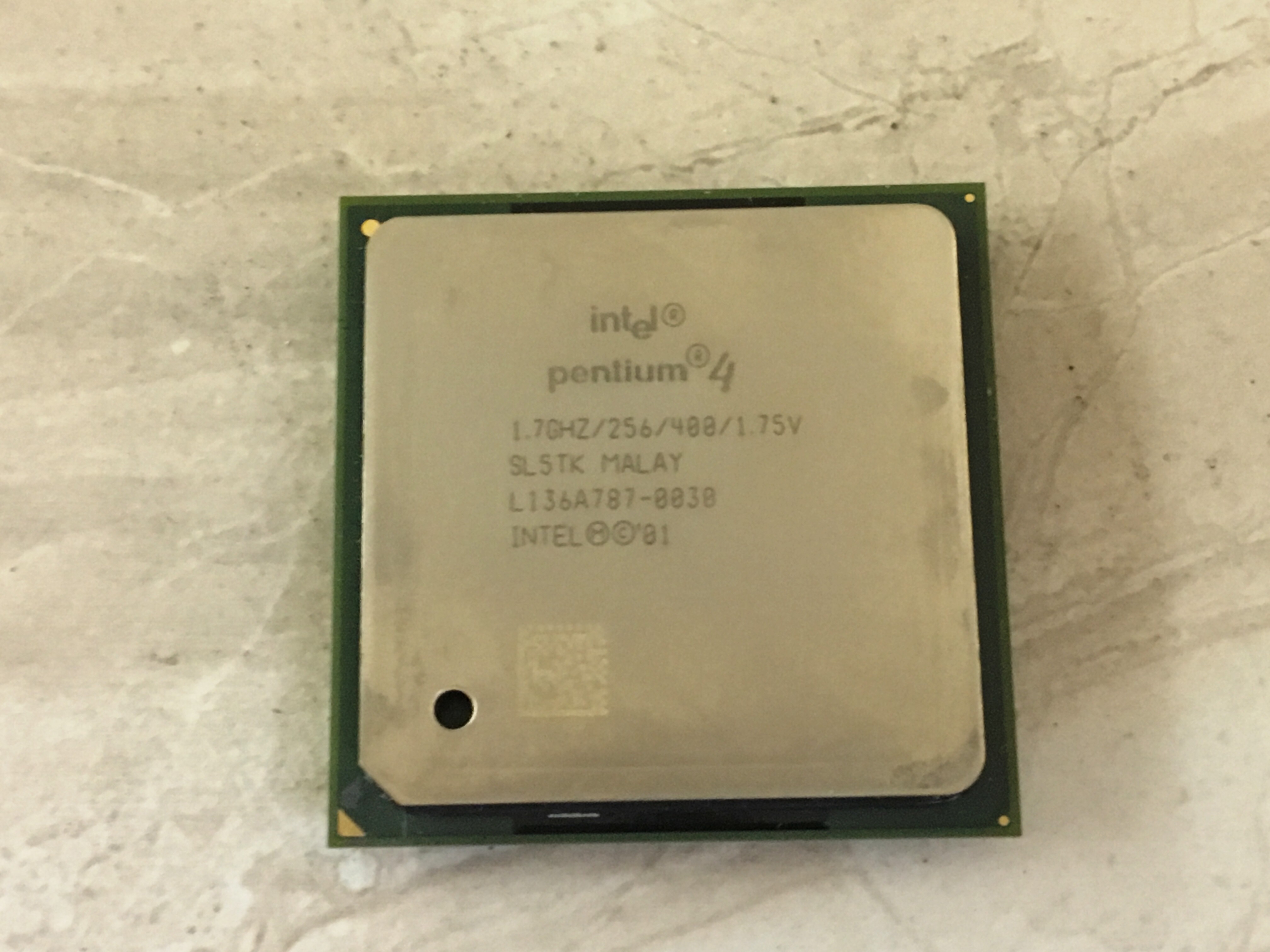
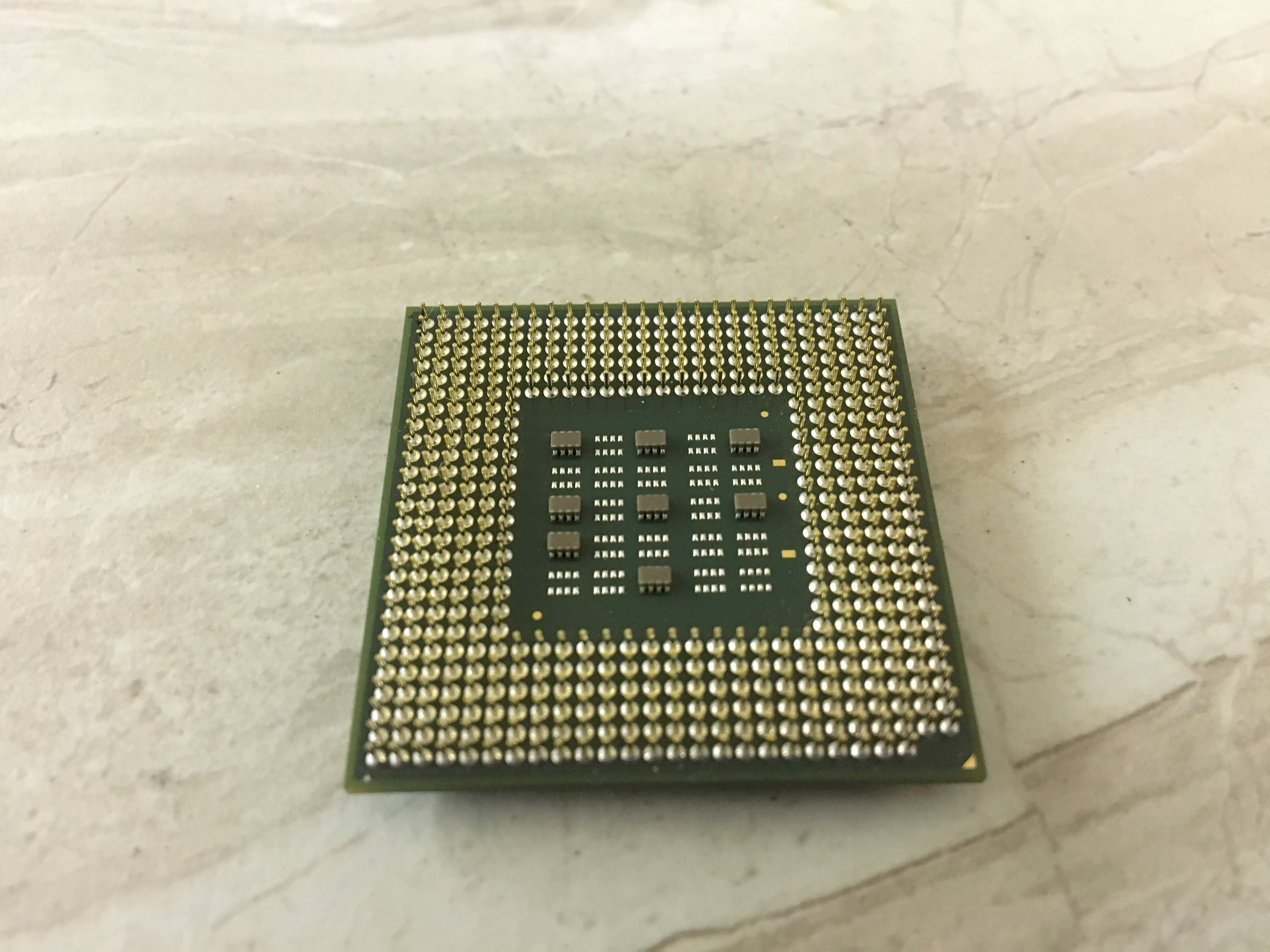
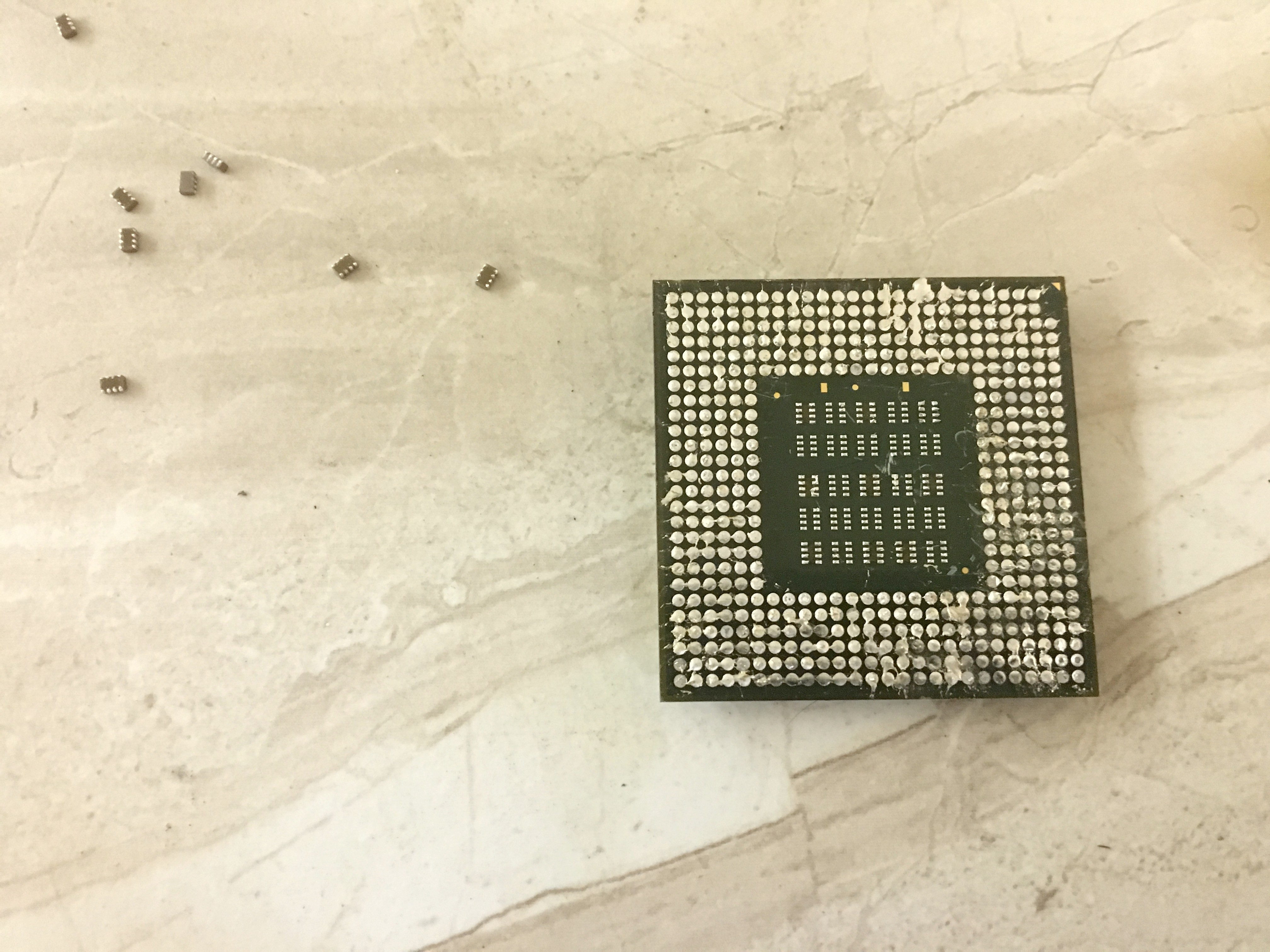
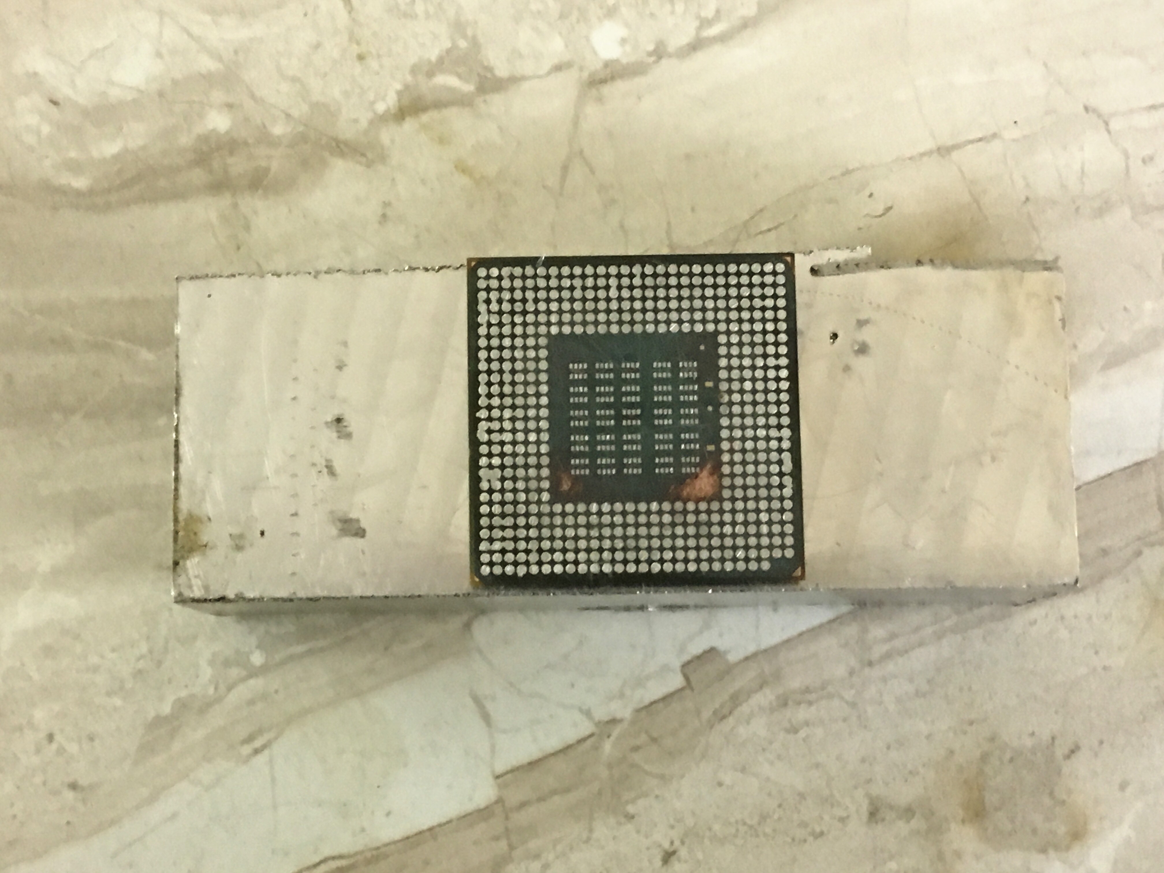
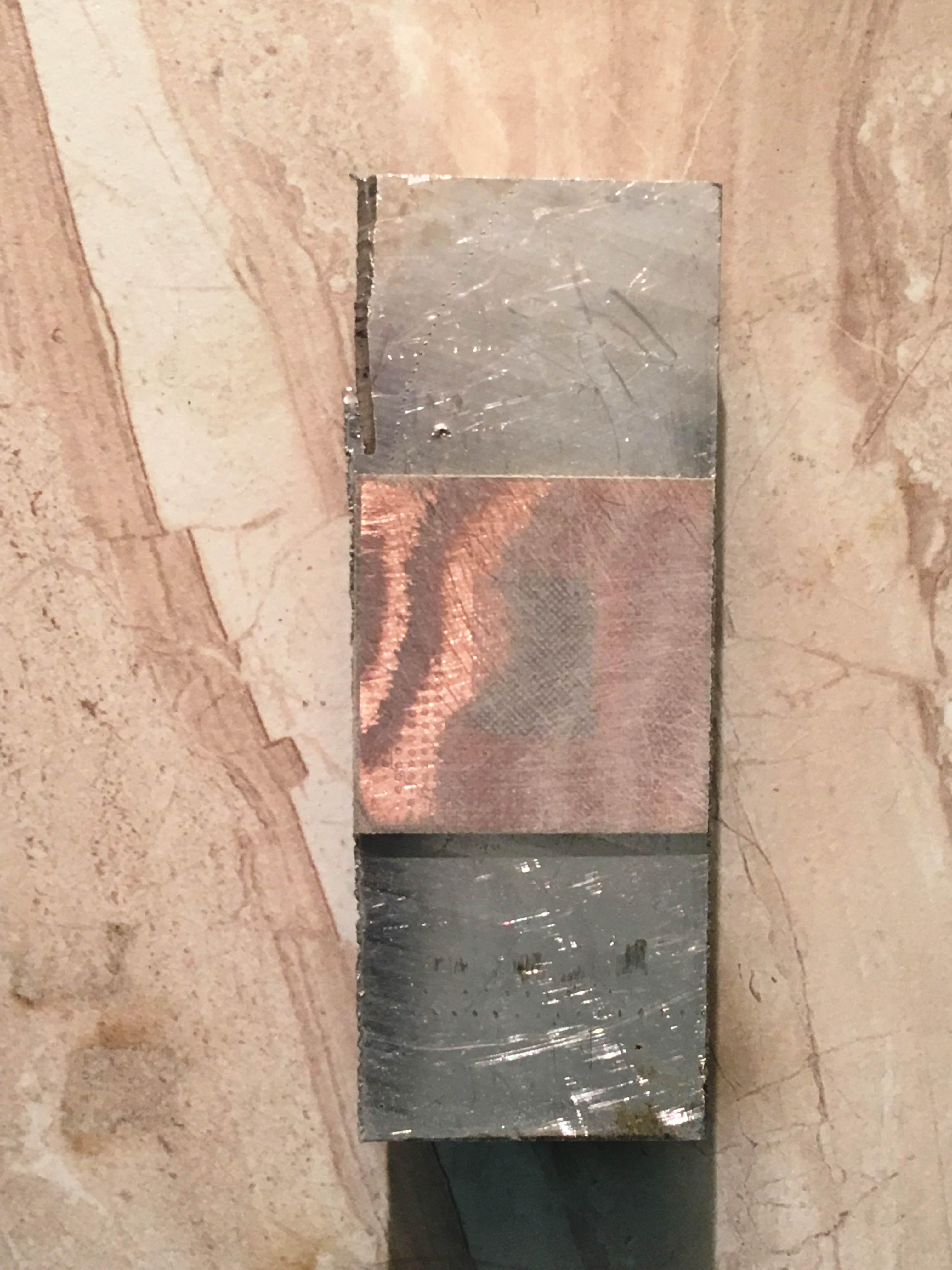
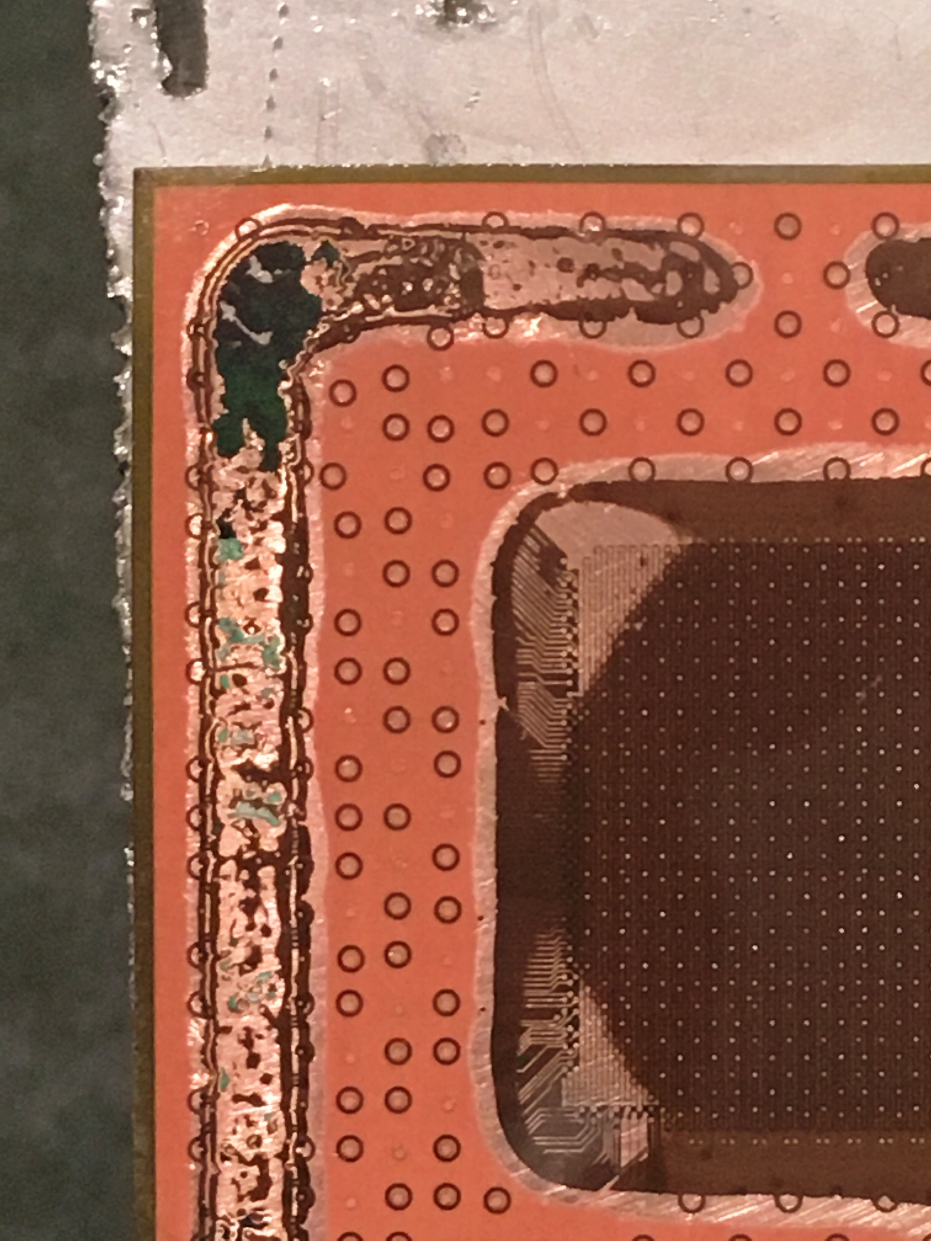
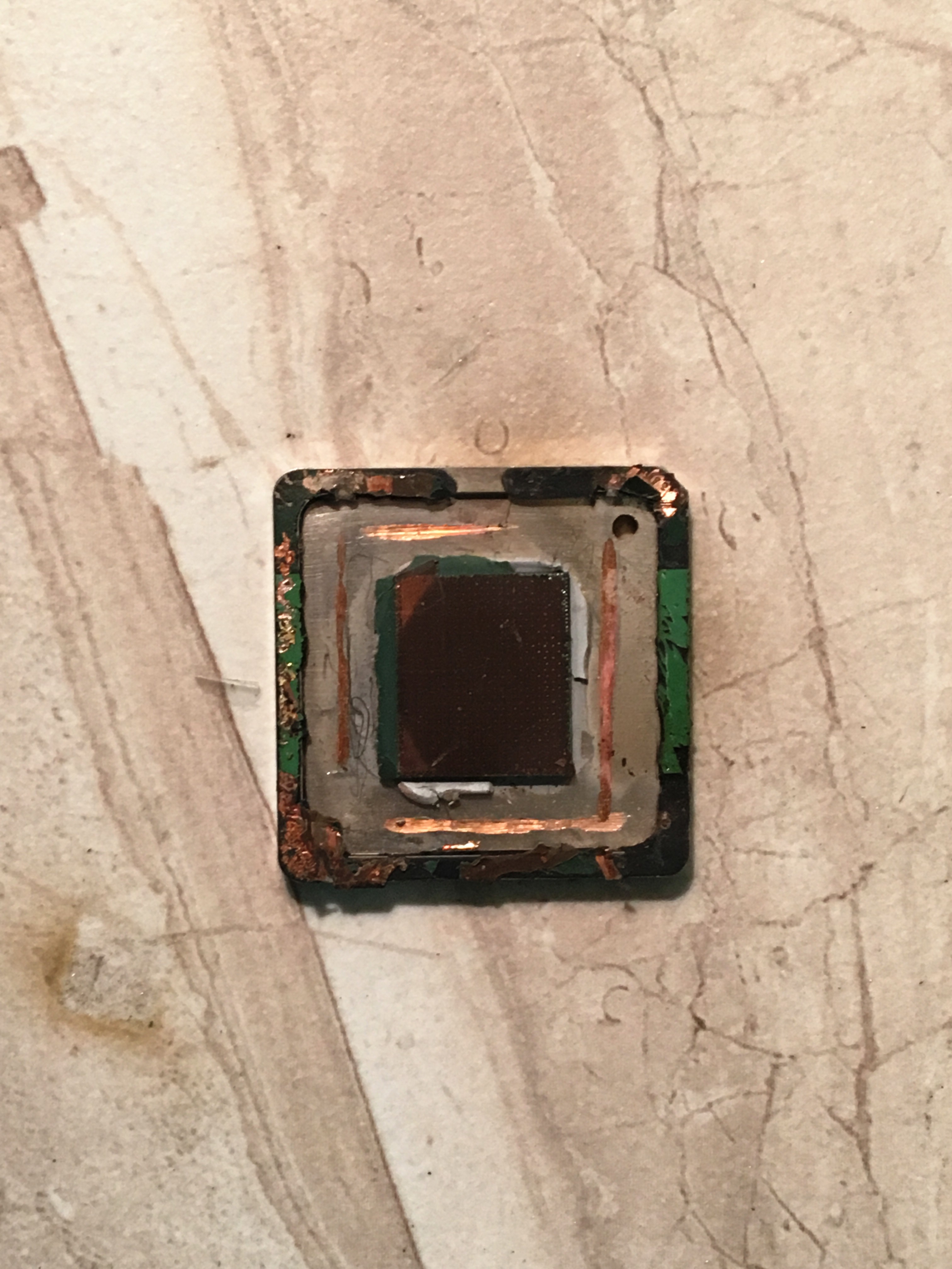
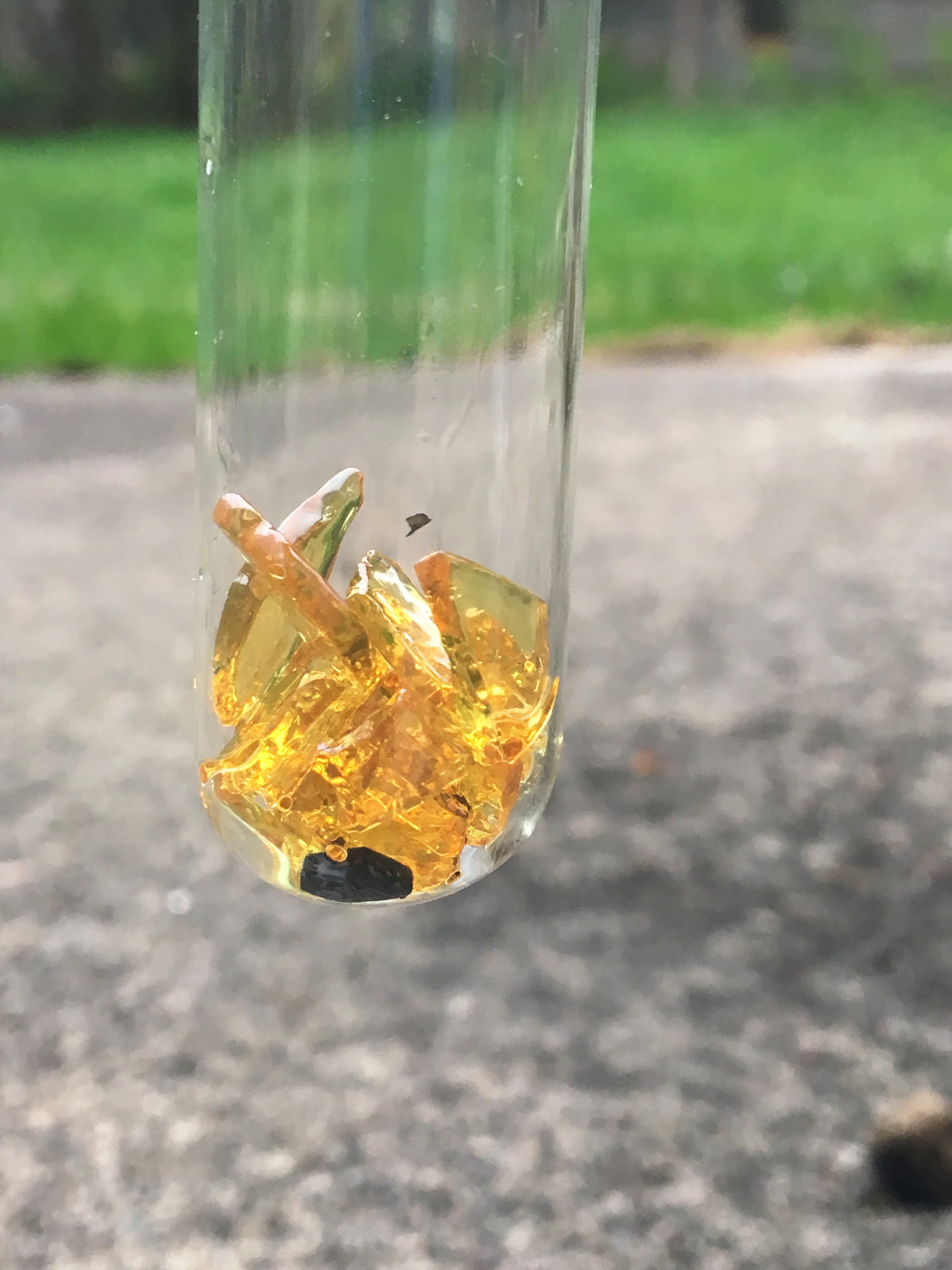
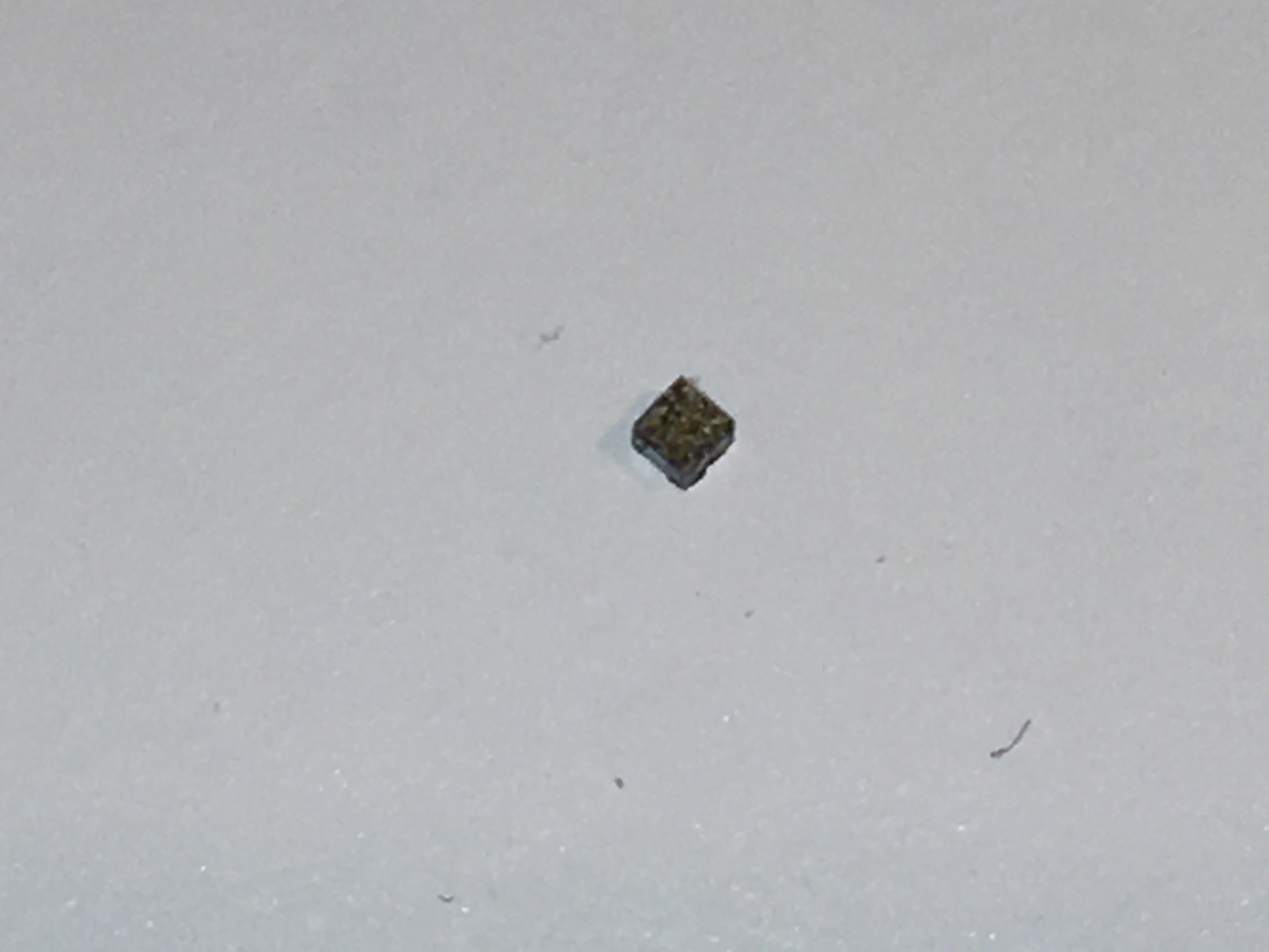
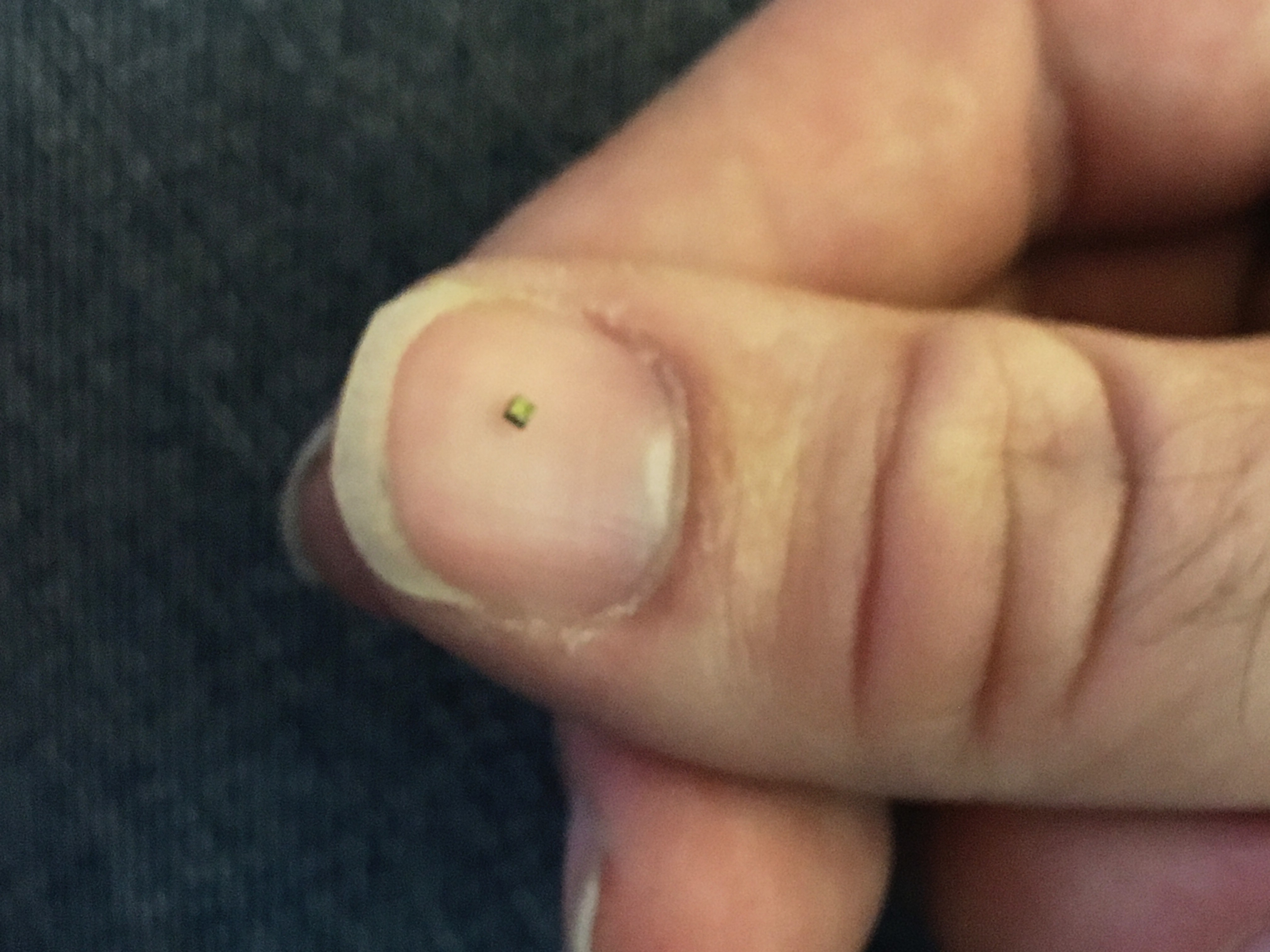
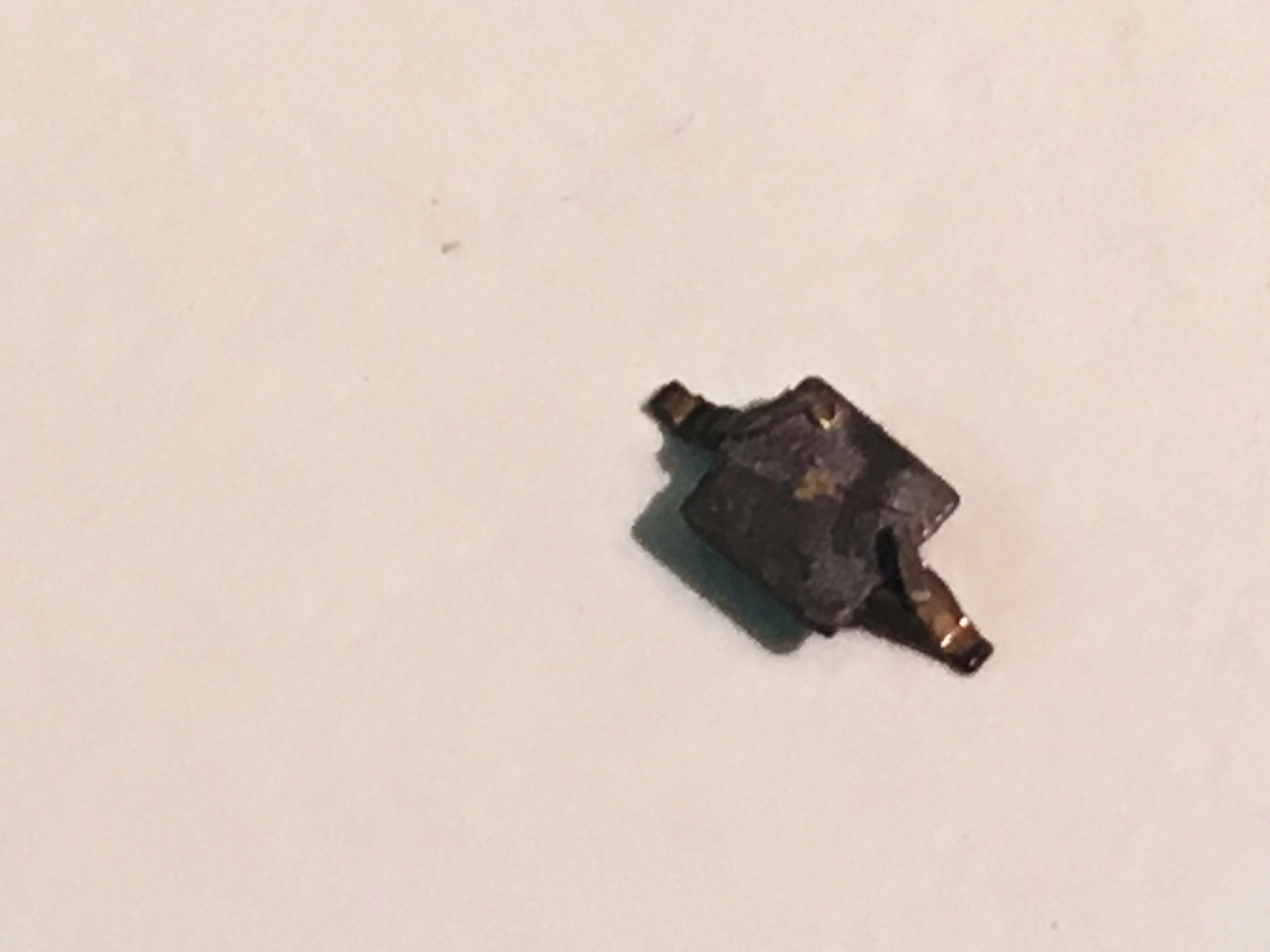
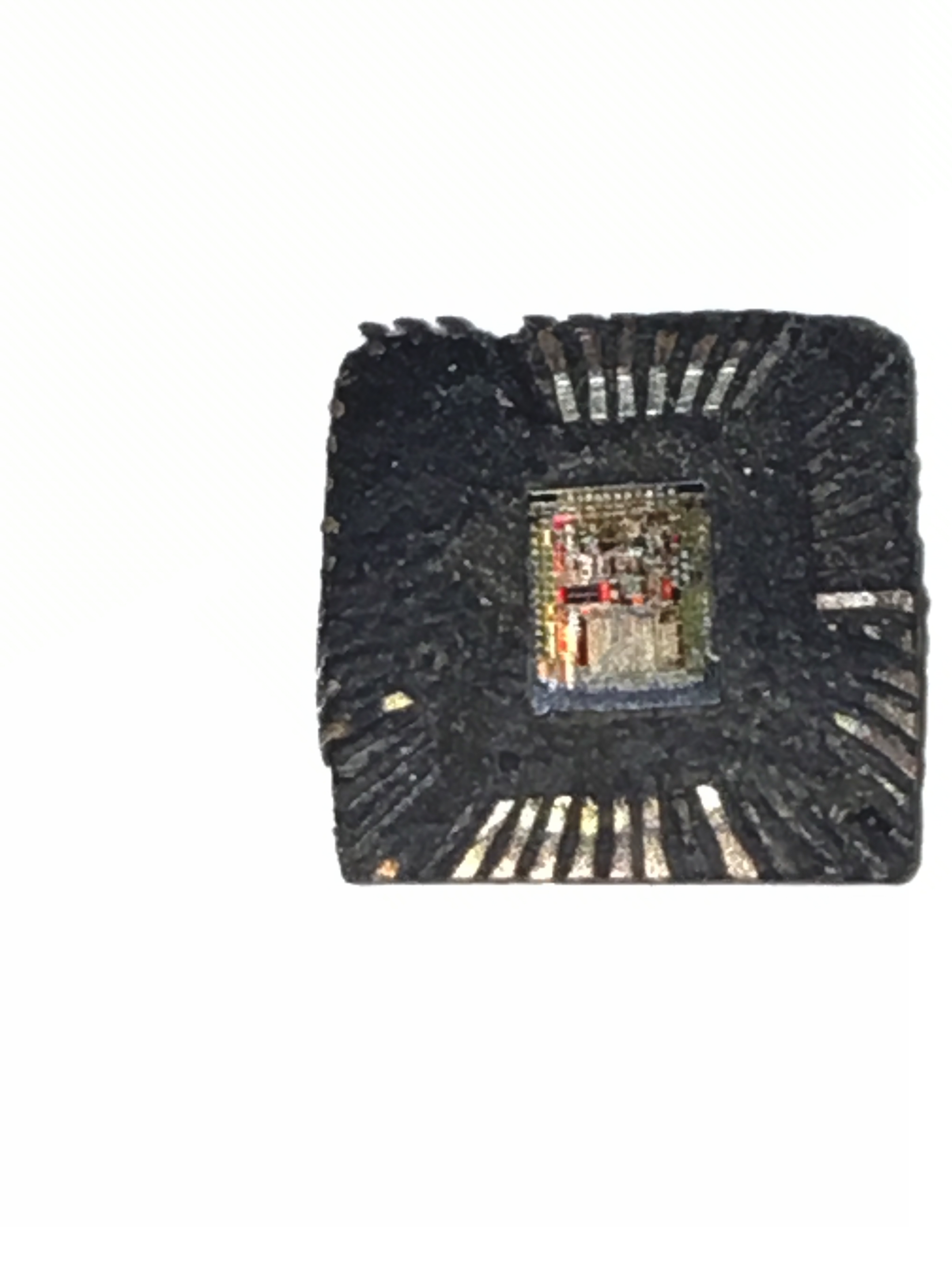
So far boiling in rosin has proven to be a very effective means of destroying IC encapsulation, exceeding my expectations. However it is most effective with some prep work, especially sanding and cutting off the pins or solder balls of the package first. I'm still perfecting the process and am on the lookout for other methods, since while cheap and easily available online pure rosin is not something you'd normally find at a hardware store. I've also had some success with simply sanding and using careful heating to reveal dies, with no chemicals required.
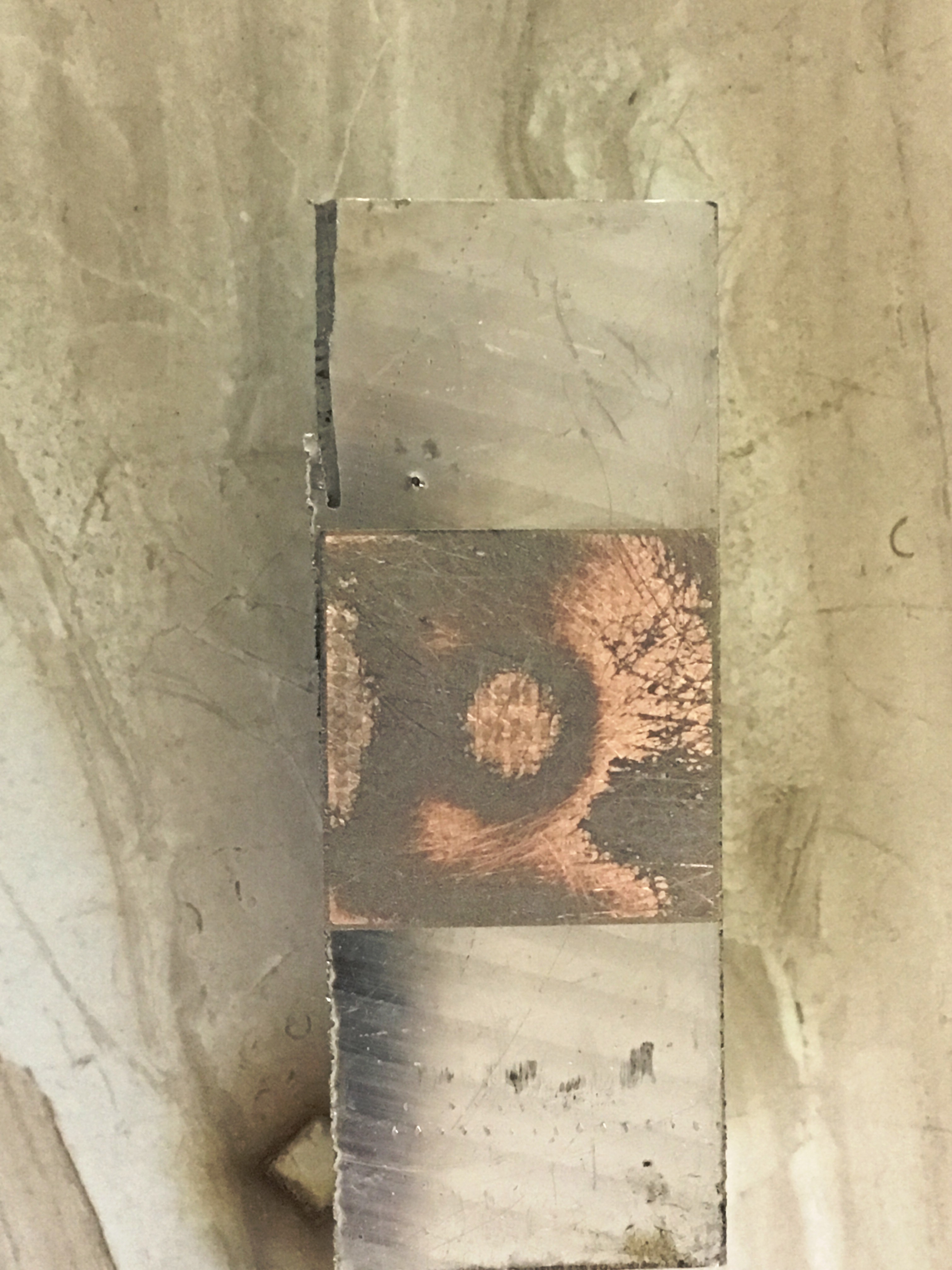

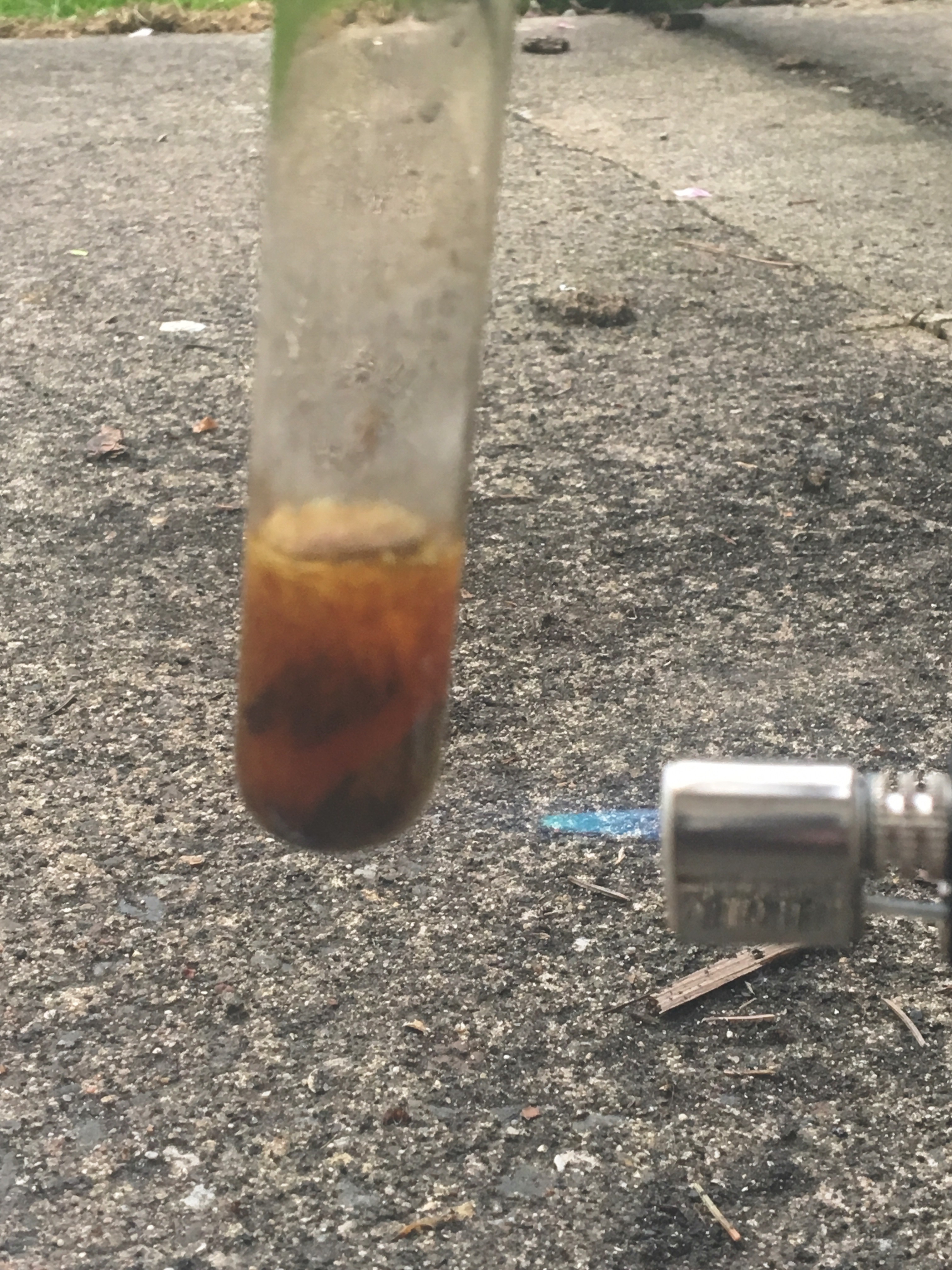
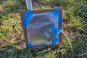
 Heat to a rolling boil for 20 minutes. Notice that I am doing this outside. The smoke you make while soldering is from the flux that solder uses, so as you can imagine boiling a couple milliliters of the stuff produces quite a bit of smoke. Also dress appropriately: rosin boils at over 300 degrees Celsius and is very sticky, you don't want to get it on your skin! Fortunately it doesn't pop and spit nearly as much as the rosin flux did, but I was wearing long sleeves, welding gloves and a face shield. That may be a bit overkill but after getting paint stripper in my eye a week ago I'm not taking any chances!
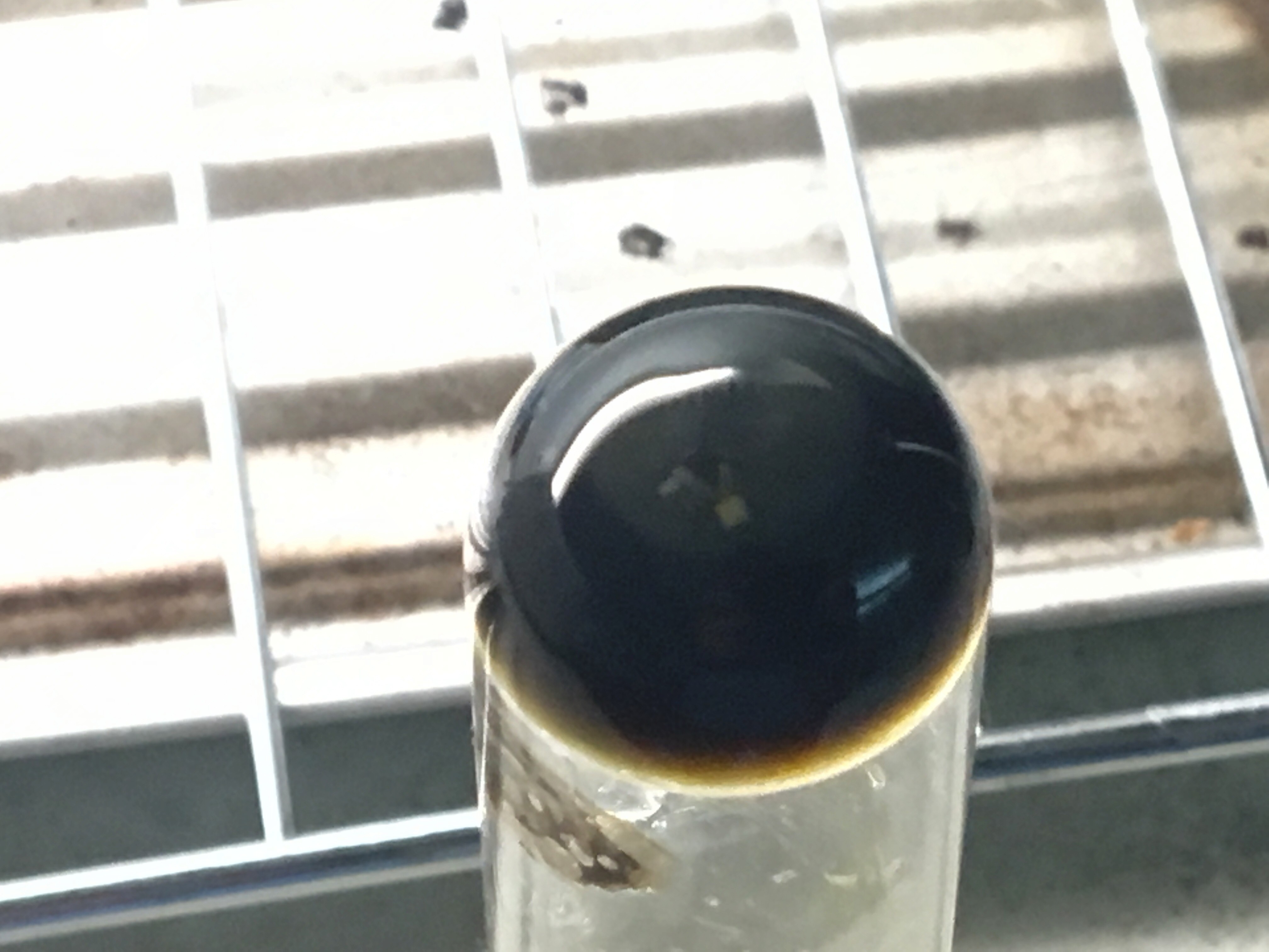
 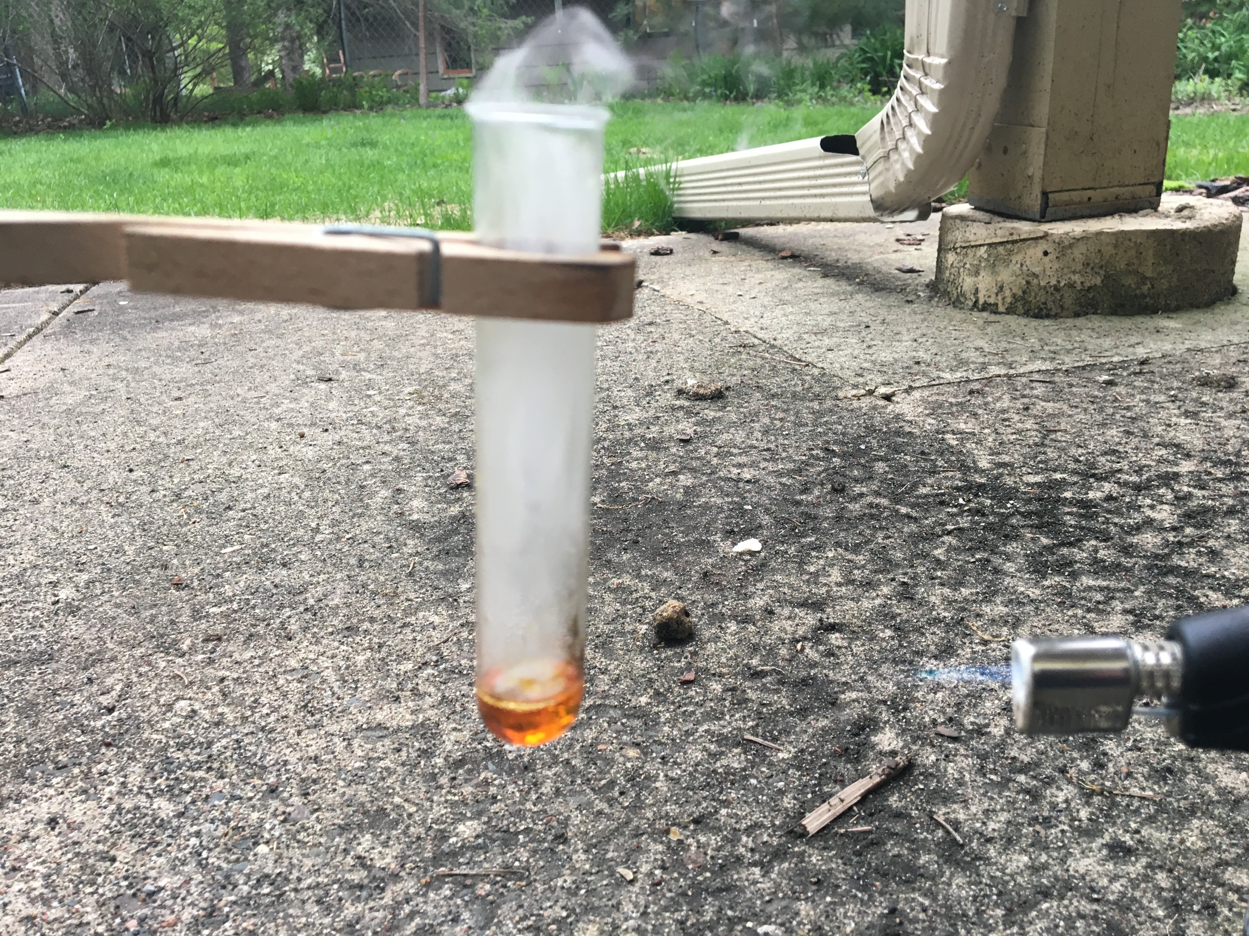 As you boil the rosin it will become dark as it eats away the encapsulation.
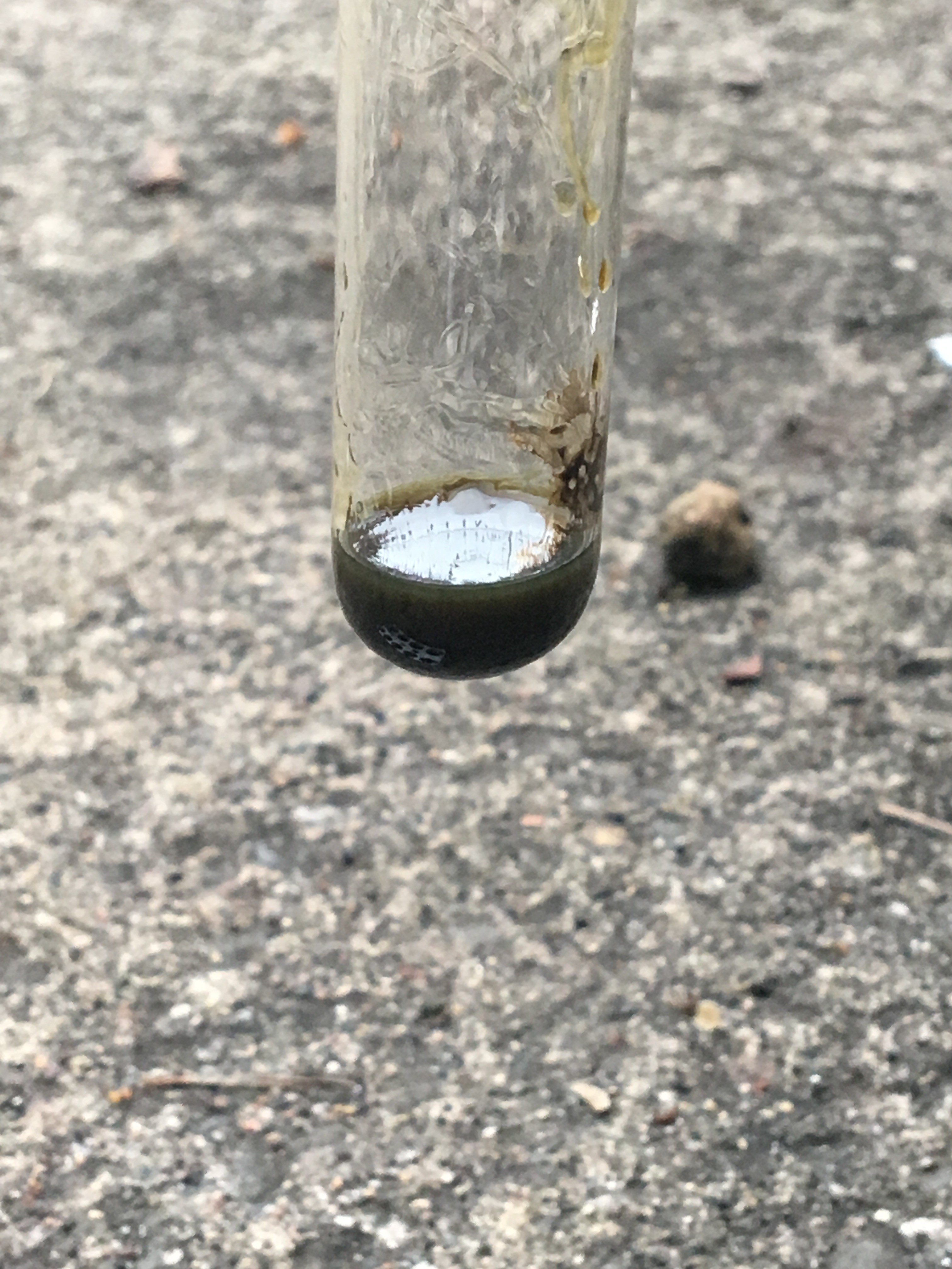


 morgan
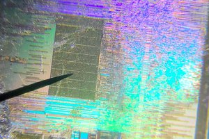

 T. B. Trzepacz
Thanks for sharing, didn't know about the Rosin method, just bought some to try it myself. I've tried the sandpaper and milling/CNC method to mild success. CNC was better as it keeps planarity with the chip well. I glued the IC to a pre-levelled bit of aluminum first to keep it more level also. Here's a video of one I did: https://youtu.be/Q9L0fKExwrI