 Michael G
CAD:
CAD data is available so you can build or contribute to Spike!
License:
Spike the Robot Dog is licensed under the Attribution-NonCommericial 3.0 United States license (CC BY-NC 3.0 US).
An open-source four-legged robotics platform
Already have an account? Log in.
To make the experience fit your profile, pick a username and tell us what interests you.
CAD:
CAD data is available so you can build or contribute to Spike!
License:
Spike the Robot Dog is licensed under the Attribution-NonCommericial 3.0 United States license (CC BY-NC 3.0 US).
Robot Dog.STEPA STEP file allowing users of any CAD software to interact with, make changes, and contribute to Spikestep - 44.46 MB - 05/14/2019 at 20:27 |
|
|
Robot Dog.SLDASMSolidWorks Assembly of Robot Dog; make sure to download the folder of files and subassemblies from the DropBox link in the descriptionsldasm - 14.28 MB - 05/14/2019 at 20:19 |
|
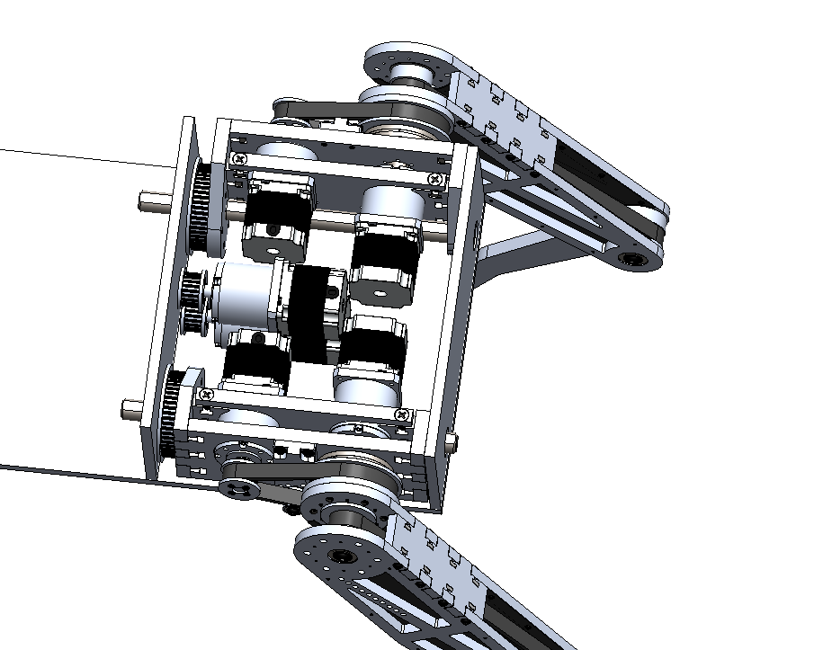
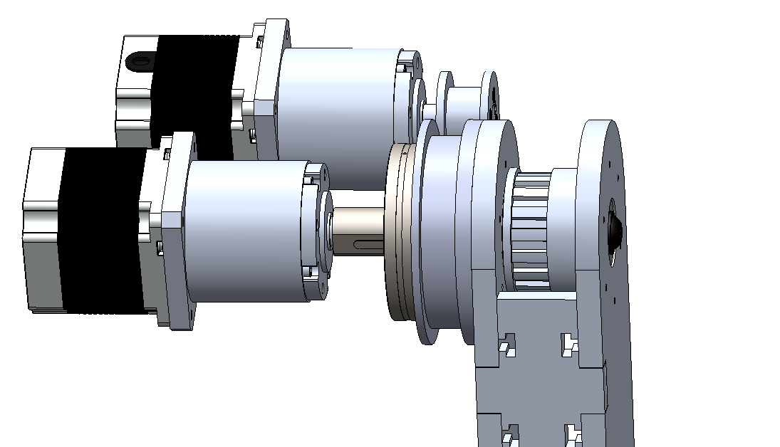
Powering the Hips:
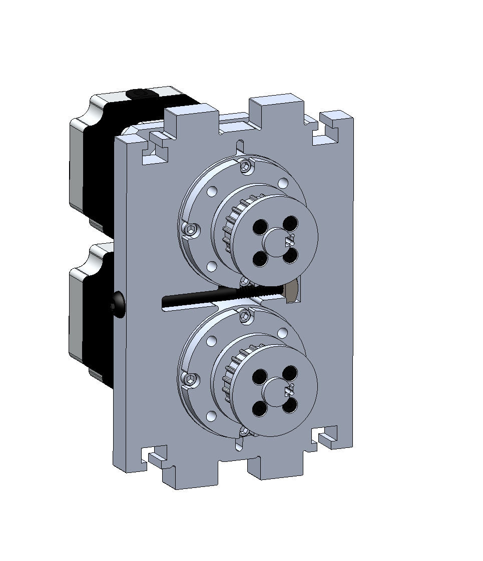
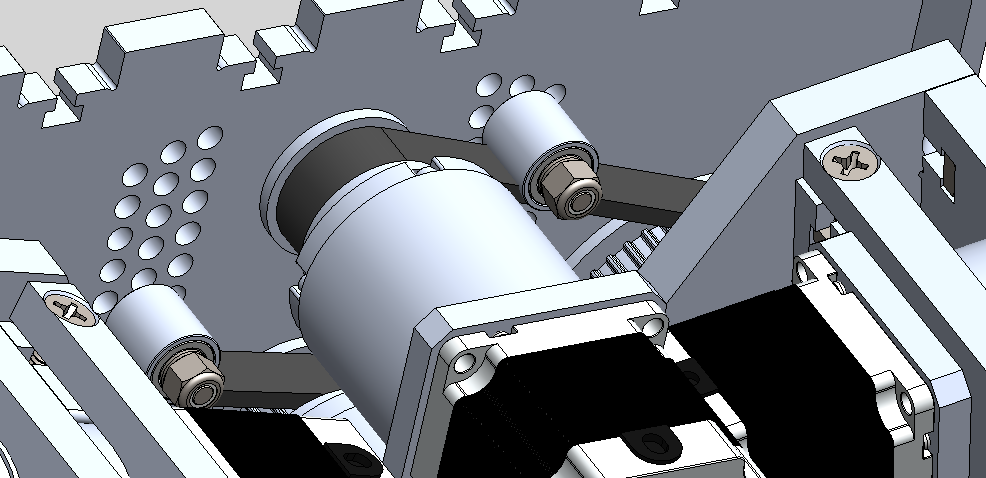
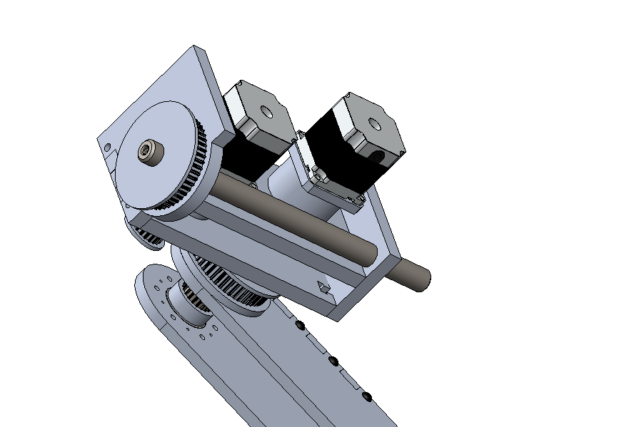
At this point, Spike still needs power to his hips. As discussed in a prior log, the two hip motors are going to be placed in the dead-space between either side’s Leg Motor Box. The hip motors are 15:1 planetary gearbox Nema 23 stepper motors, that get actual power to the hips via a AT-5 timinb belt. It’s worth mentioning here that the plan is to waterjet the zero-backlash timing belt pulleys to reduce cost. Using this manufacturing process, it’s also possible to machine the bore and a key slot to transfer the torque from the planetary output shaft to the pulley.
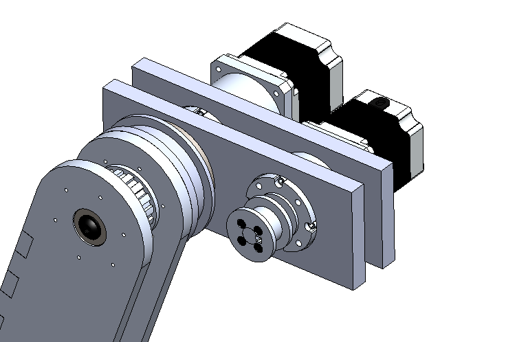
The plan is to have the motors arranged one-atop-another to get them in the limited space in between the Leg Motor Boxes. Accordingly, I adjusted the height of the Leg Retention panels and other side panels such that there was room for two of the stepper motors one-atop-another. I then designed another flexure motor mounting plate to clamp the two motors in place.
As per the standard in the design of Spike, we’re letting the machines doing the work and taking advantage of the manufacturing process of waterjet or CNC-machining. Notice how the only post-processing work necessary on this part is to drill a hole in the side of the aluminum to allow the bolt to pass through to actually clamp the motors in place.
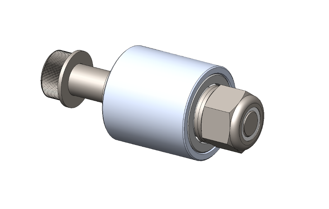
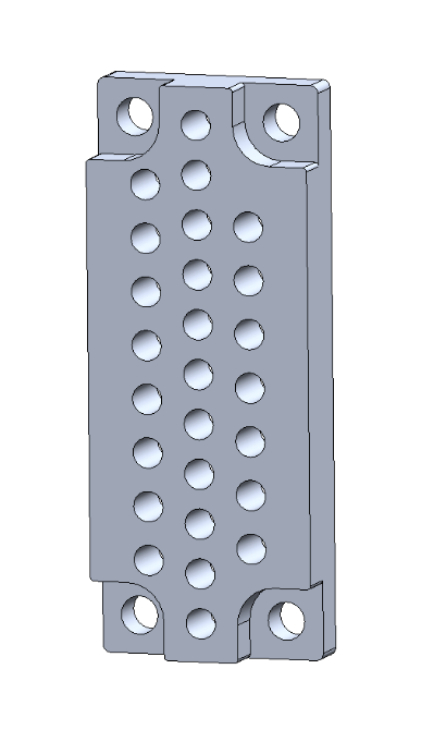
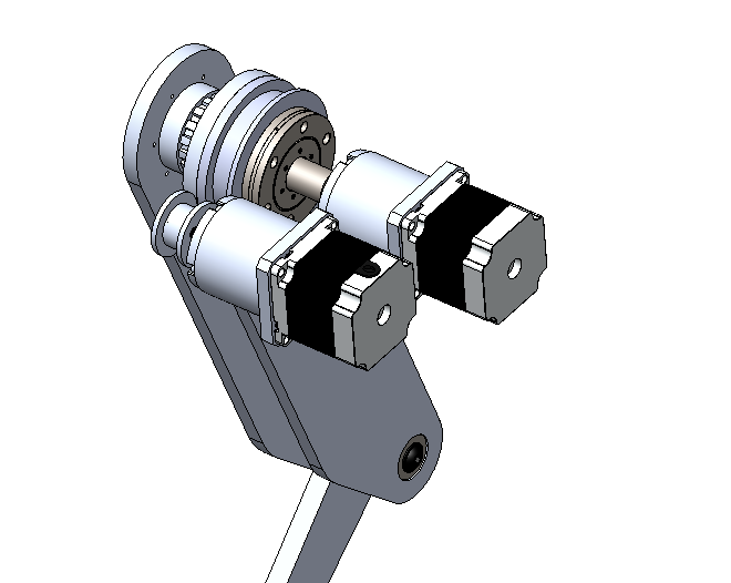
At this point I found the length of the AT-5 timing belts and mocked them up in the design. Of course, when I actually order the timing belts, they will be close to the right size, but certainly won’t be tensioned perfectly. I decided to again turn to the step-wise tensioning method talked about in an earlier log, but had to approach it a little differently to last time given space constraints. Since there won’t be accessibility to get an allen key in to screw a idler/tensioner into a tapped hole, I decided instead to use the waterjet to cut ¼” holes into the inner Leg Retention Plates.
As the holes aren’t tapped, the design was changed to leverage shoulder bolts going all the way through the holes, through the inner race of the bearing, and then tightened on the end by a nut onto the shoulder bolt’s threads.
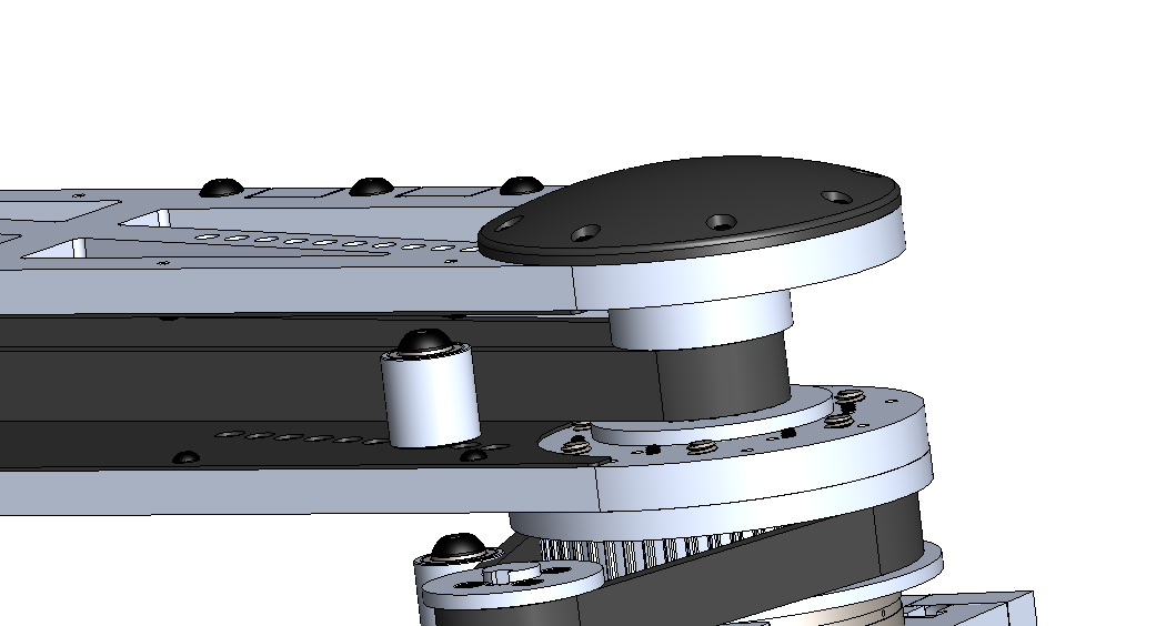
As can seen below, one of the motor’s timing belts goes to one leg, while the other goes to the other leg. The series of holes in the inner Leg Tensioning Plate allows the adjustment of tension in both of the timing belts. While the assembly is quite tight, after some adjustment, there are no conflicts between the six degrees of freedom in Spikes front or back legs.
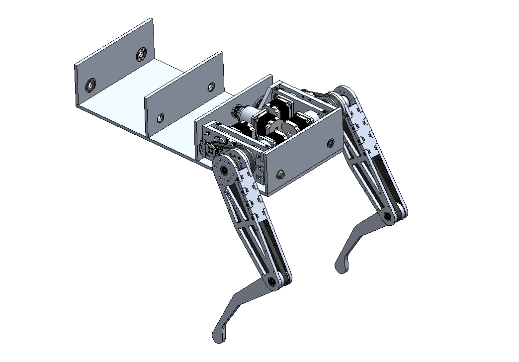
All Four Legs and Continuing the Design of Spike’s Body:
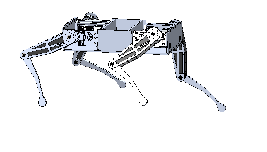
Next up, Spike needs two more legs. As discussed in the prior log, all this involves thanks to the modular design is to mirror the Leg Motor Box Assemblies relative to the Leg Motor Box Assemblies relative to the other side (front-back), as the legs all bend in the same direction at the olecranon joint. At this point, I also found it worthwhile to add side plates to Spike’s center to help retain the battery compartment.
It’s also apparent that Spike’s doesn’t have much room left for the many stepper drivers and onboard electronics. This is because I plan to add these later to the exterior of Spike, and protect them with sheet metal panels, as I imagine I’ll spend quite a bit of time under the hood of Spike. In the picture below, you can see Spike with all four legs for the first time – finally starting to look like something!
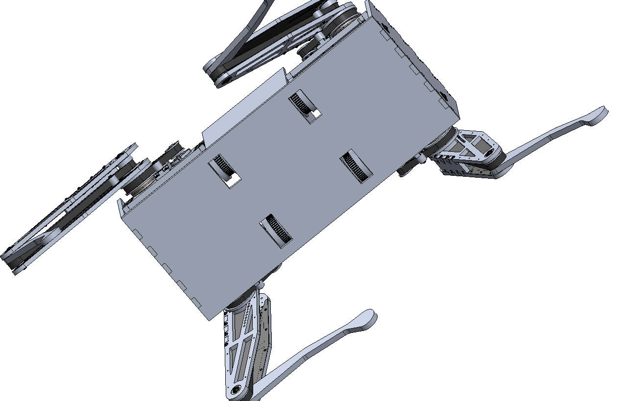
I also noticed an additional clearance issue with the Leg Motor Box Assemblies; the pulley of each assembly is conflicting with the Lower Main Plate. To remedy this, I designed a cutout four each Leg Motor Box pulley. Since these parts are designed to be either waterjet or CNC-milled, adding this through cut-out feature adds very little effort or cost.
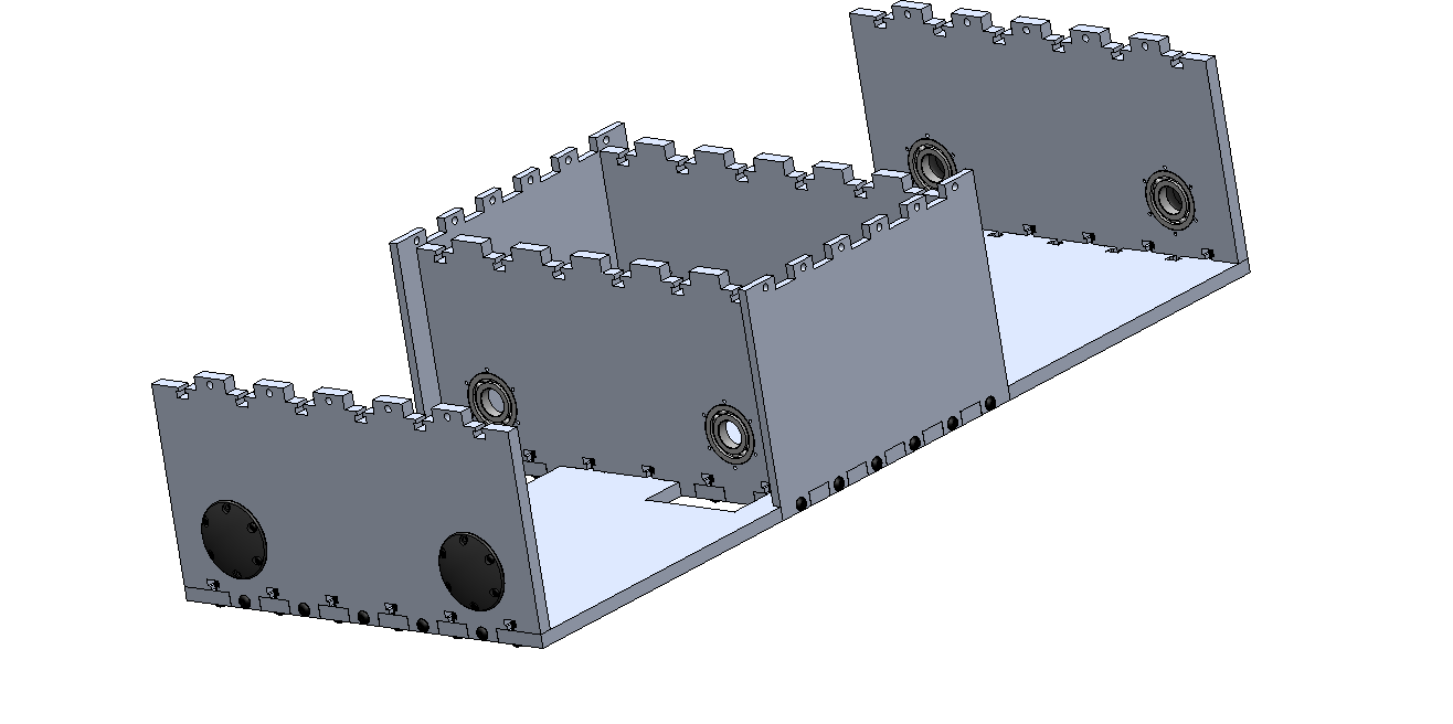
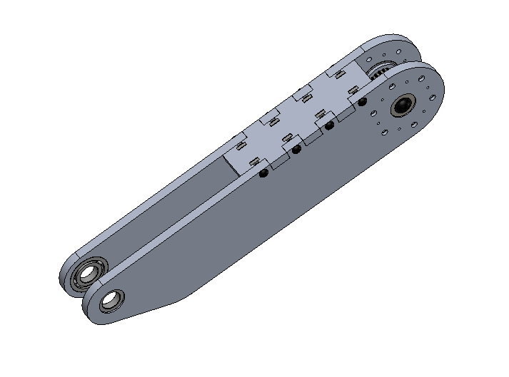
Now that Spike’s body is coming together, I decided to invest some time adding the box-joints and bolt-nut holes that will allow Spike to be easily assembled. Similar to the upper legs, Spike’s body is designed specifically for easy assembly, with all the features necessary to hold panels together cut during the waterjetting process when the panels are made. Also, as the four outermost bearings that allow for hip motion were still exposed, I designed a smaller 3D-printed bearing cover to shield the bearings from any contaminants.
Starting Spike’s Body and Adding a Leg:
Now that we have one leg completely designed, we simply need to appropriately mirror the Leg Assembly appropriately to go in each of the four locations. Note that since, the legs are all designed by default to bend their joints in the same direction (essentially all the legs are designed as “front legs”, as anatomically the joints in the front and back legs of a cheetah bend anti-directionally relative to one another). Therefore, the legs themselves are identical front to back, but mirrored side-to-side, while the Leg Motor Box is mirrored both front-to-back and side-to-side. This approach ensures that Spike has the widest possible stance for his size and makes sure Spike’s body is as compact as possible.
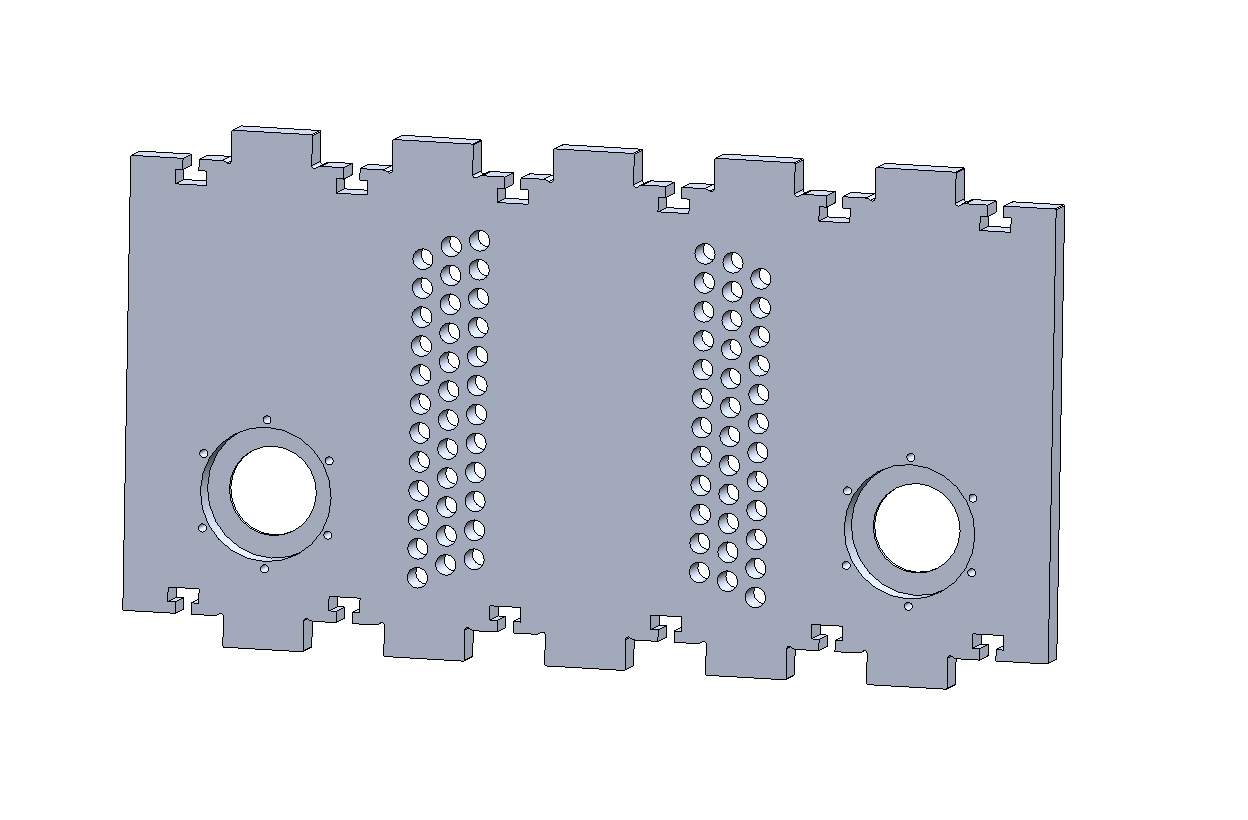
I started by creating a rectangle in SolidWorks the size that I roughly wanted Spike to be as the Main Lower Plate. Once I had a rough size determined I added two vertical Leg Retention Plates, each with two holes for press-fit bearings with a ¾” inner diameter. The inner races of the bearings will be captured on both sides, with the hole assembly pulled together by two 5/16” bolts, pulling the inside of the bearings’ inner races against washers placed on the ¾” hip D-shaft pressing against the Leg Motor Box’s side plates.
At this point I was unsure where exactly to fit the two motors per side (referring to front-back) needed to power Spike’s hips. To start, I lengthened the Main Lower Plate to provide some room for batteries right in Spike’s belly and added two more Leg Retention Plates on the opposite side of Spike. I also mirrored one leg to check for clearance issues during hip rotation, and then accordingly tweaked the motor placement in the Leg Motor Boxes and changed the bearing-to-bearing distance in the Leg Retention plate to fix clearance issues during hip movement
Now that I had fixed the clearance issues during hip movement, I realized that there was sufficient space in between the Leg Motor Box Assemblies on each side to fit two more Nema 23 Stepper Motors with 15:1 planetary gearboxes, as used everywhere in Spike so far. For now, I’m leaving them in rough position, and I’ll add a waterjet flexure motor mount later on.
Tensioning Timing Belts and Light-weighting the Legs:
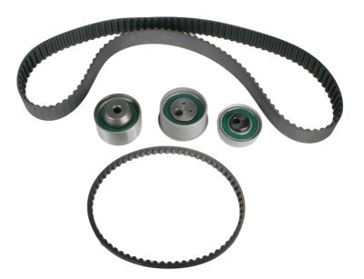
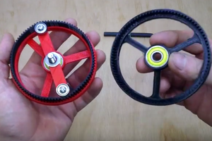
Up to this point in the design of the Leg Assembly, the timing belts haven’t had a method of tensioning. Normally in timing belt system design, an idler with an offset cam is utilized to provide the desired amount of tension (shown in the first picture below). However, I was unable to find a vendor for an offset cam timing belt tensioner that fit within the limited space and budget.
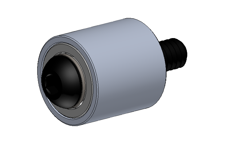
I designed a simple alternative solution. Instead of an offset-cam tensioner, I decided to add a plate to the Leg Motor Box Assembly with a series of ¼”-20 tapped holes at various heights. This plate enables small idler pulleys (essentially ¾”-diameter aluminum with two pressed pulleys to be mounted into any of the holes, providing any stepwise desired amount of tension.
I then continued by adding a similar tensioning mechanism to the upper-leg assembly. Rather than three rows of offset holes, the longer geometry of the upper leg allowed me to add fewer holes at a small angle to the length-wise side of the edge of the timing belt that powers the lower-leg. For cosmetic reasons and to keep dust out of the upper-leg bearings, I also decided to add a 3D-printed bearing shield. In the short-term (just after the design is finished), I’ll print these on a Form 2 of Prusa – long-term I’ll have them printed very inexpensively using Multi-Jet Fusion through a 3D printing service bureau.
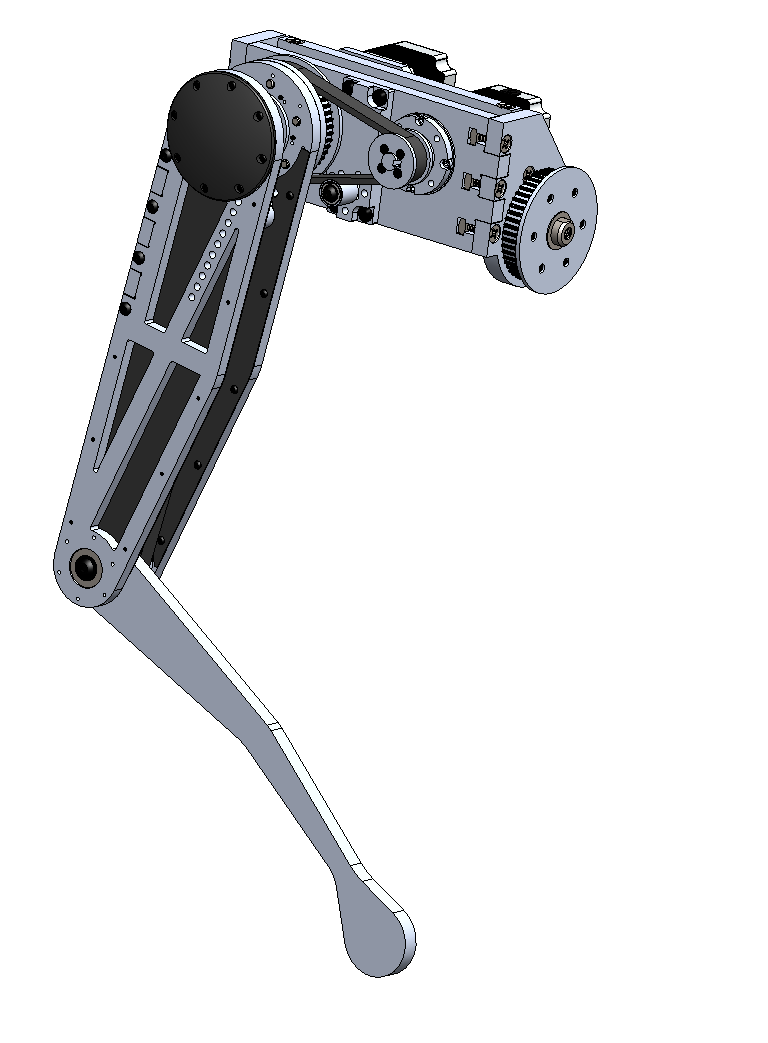
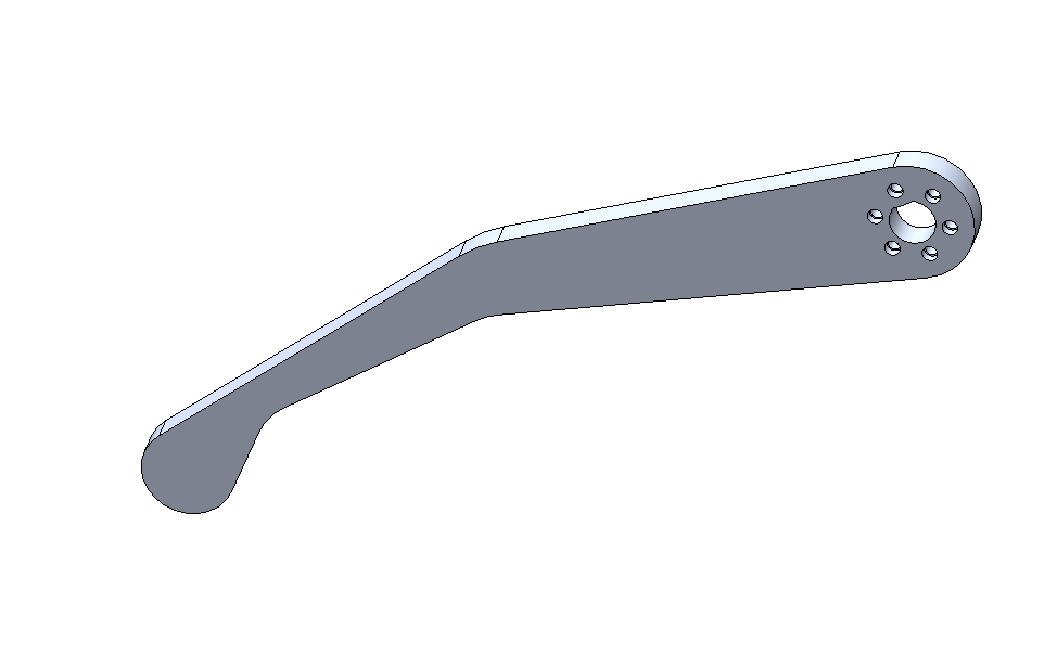
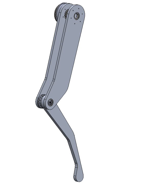
In order to minimize rotational inertia in the upper legs, I spent some time light-weighting Spike’s upper legs, while being sure to keep enough material to make sure the tensioner inside the upper leg assembly operates without issue. I also added waterjet carbon fiber plates to the inside of Spike’s legs for some additional rigidity and to make Spike more cosmetically-pleasing, though this step is unnecessary if you’re replicating Spike (unless you like the look, of course!). At this point, a full Leg Assembly has been designed designed, complete with an upper-leg, lower leg, and hip joint to provide three degrees of freedom. From here, I’ll have to mirror this assembly for the other three legs, and begin designing Spike’s body.
Designing the Leg Motor Box:
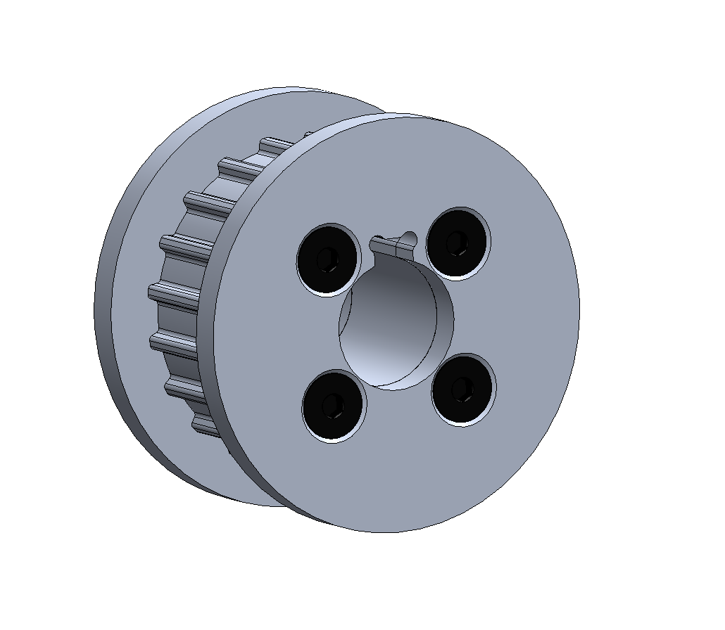
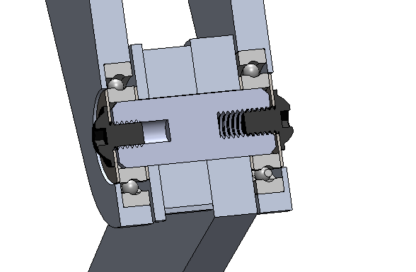
To make it a little more clear exactly how torque is getting to the lower pulley that is attached to the side of the lower leg, I’ll start this log with some further discussion of power transmission. In the picture below, notice how the ¾: D-shaft from the upper-leg assembly goes directly through the 20mm center of the crossed-roller bearing that holds the leg assembly to the Motor Box assembly. This is such that the D-shaft can be drilled on-center to a slip fit for the outer-diameter of the planetary gearbox’s output. A slot will be milled through the side of the D-shaft above the on-center hole to allow a key to drop-in to the transmit torque from the keyed shaft of the planetary gearbox output to the upper-leg D-shaft.
Recall from previous logs that the upper-leg D-shaft, unlike the lower-leg D-shaft, does not serve to mount the upper leg to the Motor Box Assembly, as such is achieved via the crossed roller bearing. The D-shaft instead only is meant to accept torque from the planetary gearbox and transmit that torque (via the D-shaft) to a pulley. One notable down-side of this design style, in addition to design complexity, is that when the upper-leg moves, the lower-leg will not completely move translationally with the upper leg (the lower-leg will rotate one way or the other relative to the upper-leg if only the upper-leg motor moves). However, this can be completely counteracted in software.
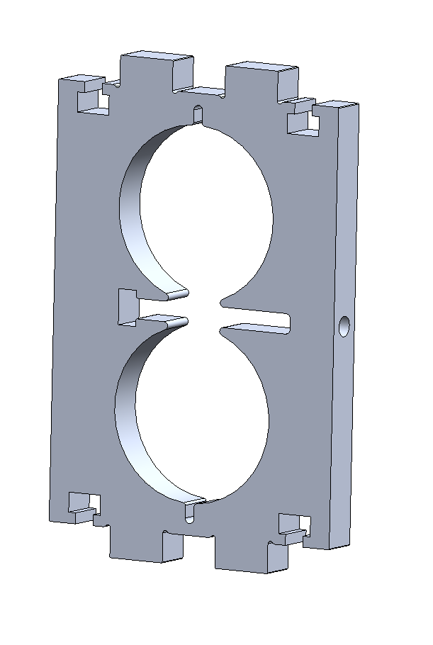
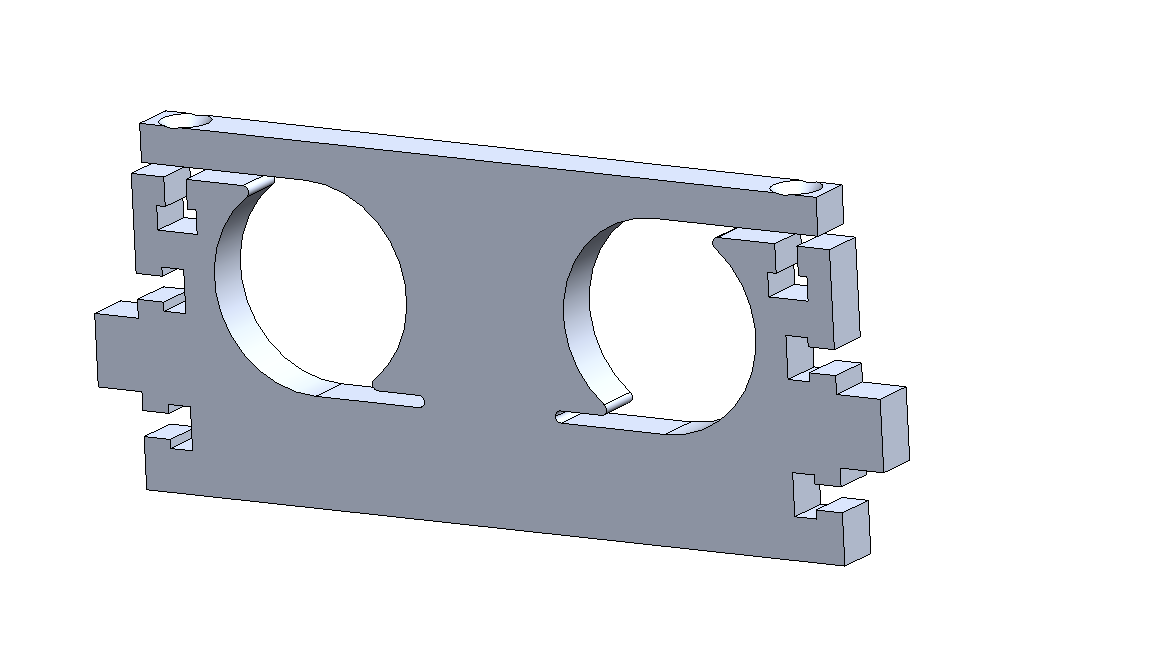
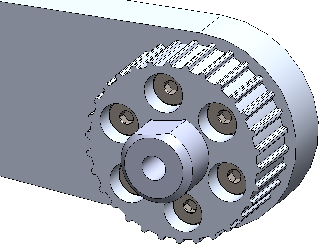
After I had the basic concept getting power to the legs, I began to flush out the design of the Leg Motor Box Assembly. The Leg Motor Box Assembly was designed to be completely waterjet, with box-joints and slit and square-nut assembly. The design for the Leg Motor Box Assembly began with two waterjet plates, one to mount to the crossed roller bearing and one to provide a motor mounting plate. I also decided to leverage the manufacturing process of waterjet by using a flexure to mount the motors while minimizing part count. A flexure is essentially a component that is designed to bend or flex in one or more directions to replace some form of actuation – in this case, cutting strategically cutting slots in the Motor Mount Plate in the Leg Motor Box Assembly, which clamp onto the motors to keep them in position when two bolts are tightened. I then added two side plates to connect the first two plates into one subassembly.
A ¾” D-shaft was also added, going through the two Side Plates in the Leg Motor Box Assembly; the D-shaft was is locked from rotating by a waterjet D-shaft profile in the side plates. Further, one of the side plates is larger than the other to accept a waterjet timing belt pulley. This pulley, analogous to the pulleys discussed previously, has a D-shaft profile cut into it, with additional torque-transfer and assembly with shoulder bolts. Just as with the other two degrees-of-freedom per leg, the hip joint will be powered by a stepper to gearbox to timing belt system. In this case, however, the hip motors will be mounted directly to the body of Spike.
Leg Power Transmission:
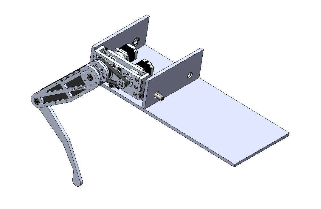
Next up was to design a method of transferring power to the two upper and lower components of each leg (i.e. the upper leg and lower leg). Thereafter, I’ll design the method to add hip movement to each leg assembly. As one of the main parameters around which Spike is being design is maximum design flexibility, I decided to prioritize Spike’s capacity to rotate its upper legs 360-degrees (infinitely in either direction) with reference to Spike’s body. This will enable Spike to walk well in an inverted state (upside-down).
I also prioritized minimizing the rotational inertia of each leg to minimize the amount of torque required for each leg. Thus, I decided it would be best for motors to not be mounted to the legs at all to minimize rotational inertia as much as possible, as well as to eliminate the need for slip rings or other electrical transmission through rotary joints. Getting torque to all the pulleys in the leg assembly (there are three) while also not attaching motors directly to any of the legs proved difficult. I started by finding a proper bearing capable of handling moment load, settling on a crossed roller bearing such that Spike’s legs could be cantilevered from the body, rather than being attached on both sides. I selected a bearing with the maximum possible inner diameter that also fit within the given design volume, eventually arriving at a crossed roller bearing with an inner-diameter of 20mm.
After trying out several ideas, I designed and mocked up a method for successfully transmitting torque to all the pulleys in Spike’s legs without mounting any motors to the legs themselves. This method, shown in a rough mockup below, involves powering the upper leg’s movement via a timing belt going directly to a timing belt pulley mounted to the side of the upper leg assembly concentric to the rotational axis. I decided that both motors would be mounted to a Leg Motor Box, that serves triple duty: 1. providing a mounting surface to the upper leg, 2. providing mounting for the two motors for the upper and lower leg, and 3. serving as the hip joint allowing the whole leg to swing out away from Spike’s body.
Placement of components in the Leg Motor Box assembly is conceptualized below. Note that the parts that provide mounting surfaces for motors, leg mounting, and hip rotation, are to be designed shortly. The next log will flush out the design of the Leg Motor Box in greater detail.
Upper and Lower Leg Assemblies:
The design started by with the lower leg. To enable 360-degree rotation and to keep cost down, it was decided to opt for steppers attached to gearboxes attached to timing belts to transmit torque. Alternatively, I could have utilized higher-reduction gearboxes, like harmonic drives or several more stages of planetary gearboxes, but these solutions would have been cost-prohibitive. Transmitting torque through timing belts also provides the added benefits of providing some shock absorption to allow guard the motors from any torque spikes or being back-driven.
¾” D-shafts were utilized to transmit torque through the timing belt pulleys to the legs accordingly, with the matching D-profile to be waterjet into the pulleys and legs (these pulleys would be fine printed in SLS or solid FDM, or the D-shaft could be turned into a key for those who would like to replicate this design using different tools). Additionally, it was decided to attach the pulleys to the lower leg with shoulder screws to pull the assembly together and utilize the shoulders of the bolts as dowel pins to allow additional torque transmission.
Next, the design for the upper legs was begun, beginning with the means of connecting the lower legs to the upper legs. Initially, the upper leg design incorporated only one upper leg for each lower-leg, but a second side was added to increase rigidity and reduce overall cost (a costlier crossed roller bearing would be needed otherwise to support the moment-load). Below, the start of Spike’s two-sided upper-leg assembly can be seen. An upper cross-brace was also added to help increase rigidity. The two-sided upper-leg assembly also ensures that two bearings can be used, with the design such that each bearing has both sides of its inner race captured and one side of its outer race captured (note that for bearing to work properly, you should “capture” as many sides of the races as possible to keep all the parts rigidly connected through the bearing assembly). Note how the whole subassembly is pulled together via two bolts pressing the inner races into the inner components between the bearings.
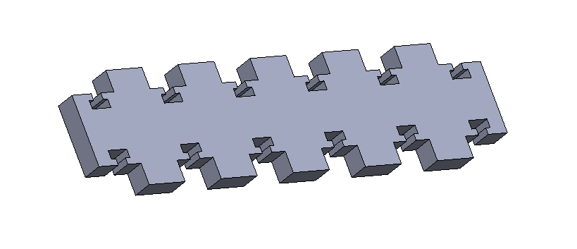
To reduce the labor needed to assemble Spike and decrease the time for Spike’s iteration cycles, joints are going to be designed in a box-joint style, where parts slot into other parts for referencing (this can be seen in the photo below). Similar to many laser-cut or milled machines from the Maker movement (like the Makerbot Cupcake, for instance), slots terminated with square holes are designed right into components to accept a bolt and a square nut, while protruding box joints and reference components for assembly. This method of design ensures that parts can come right off a waterjet or CNC mill and be immediately assembled.
Concept:
In order to build a robotics platform, I first considered the type and breadth of applications that I wished to address. As aerial vehicles are already inexpensive and available, I decided to focus on an on-land robotics platform capable of traversing terrain. Intended application areas include:
The robotic platform – called Spike [Buffy anyone?] – is designed as an open alternative to robots like Spot and Laikago the robot dogs. Critically, Spike is designed to cost less than $5,000 – rather than tens or hundreds of thousands of dollars – while also providing developers an open platform complete with source code to ensure that Spike sees the fullest possible utilization and range of possible applications.
Spike will also be designed to accept a range of modular components, including modular robotic arms and robotic end-effectors, such that the bot can be configured to achieve a variety of tasks. Similar to the approaches of Universal Robotics has taken with end-effectors for their robot arms, Spike will be capable of accepting a variety of robotics and end-effectors devices to achieve a wide range of tasks in real-world applications.
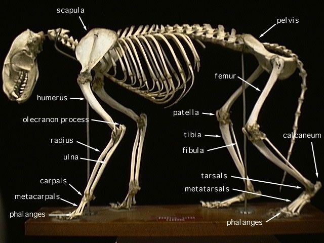
Bio-Inspiration:
The design phase started by deciding the shape and type of legs to use on the robot. As the goal is to produce a robotics platform capable of effectively maneuvering obstacles at reasonable speed, inspiration was taken from big cats.
Notably, in big cat anatomy, the olecranon rotates anti-directionally relative to the patella. Further the legs are all capable of rotation thanks to the lower legs’ capacity for the two bones to twist past one another. As the goal is to build a robotics platform that is low-cost and fully-reproducible, it will be necessary to limit the degrees-of-freedom present in the robot. Thus, the six degrees of freedom present in the legs of most mammals will be sacrificed for only three, which has been long-demonstrated as effective in robots from hexapods to existing closed-source robot dogs.
Spike is centered around four modular, nearly identical (some mirroring) leg-assemblies. Accordingly, the design phase started by designing one of these leg assemblies
As I have access to a variety of tools (including a friend with an industrial waterjet), these tools were utilized to speed up the pace of design iterations, and parts were designed for manufacture for these tools. Notably, while most parts were designed to be made on a waterjet, all of them are designed such that they could also be made on only a hobby CNC-mill, or ideally a CNC-router. Spike will use a variety of materials, though almost all critical parts will be made from widely-available, easy-to-machine, and inexpensive ATP-5 aluminum (7000 series). Solidworks was used for the design, but both Fusion360 exported and .STEP files are also provided to ensure that anyone with any budget and ability can contribute to Spike.
For the sake of simplicity, some further deviation from bio-inspiration was taken for the sake of simplify – making the distance between centers of the upper leg and the distance from the center of the lower leg to the ball of the foot identical to simplify our walking model down the road.

 Simon Merrett
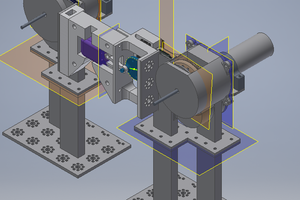
 Silas Waxter
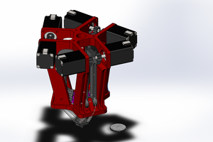
 David Brown
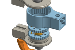
 Tim Wilkinson