 Michael G
Leg Power Transmission:
Next up was to design a method of transferring power to the two upper and lower components of each leg (i.e. the upper leg and lower leg). Thereafter, I’ll design the method to add hip movement to each leg assembly. As one of the main parameters around which Spike is being design is maximum design flexibility, I decided to prioritize Spike’s capacity to rotate its upper legs 360-degrees (infinitely in either direction) with reference to Spike’s body. This will enable Spike to walk well in an inverted state (upside-down).
I also prioritized minimizing the rotational inertia of each leg to minimize the amount of torque required for each leg. Thus, I decided it would be best for motors to not be mounted to the legs at all to minimize rotational inertia as much as possible, as well as to eliminate the need for slip rings or other electrical transmission through rotary joints. Getting torque to all the pulleys in the leg assembly (there are three) while also not attaching motors directly to any of the legs proved difficult. I started by finding a proper bearing capable of handling moment load, settling on a crossed roller bearing such that Spike’s legs could be cantilevered from the body, rather than being attached on both sides. I selected a bearing with the maximum possible inner diameter that also fit within the given design volume, eventually arriving at a crossed roller bearing with an inner-diameter of 20mm.
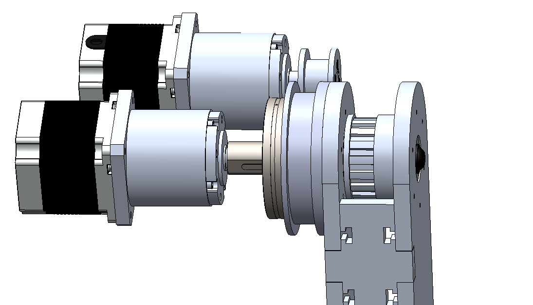
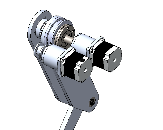
After trying out several ideas, I designed and mocked up a method for successfully transmitting torque to all the pulleys in Spike’s legs without mounting any motors to the legs themselves. This method, shown in a rough mockup below, involves powering the upper leg’s movement via a timing belt going directly to a timing belt pulley mounted to the side of the upper leg assembly concentric to the rotational axis. I decided that both motors would be mounted to a Leg Motor Box, that serves triple duty: 1. providing a mounting surface to the upper leg, 2. providing mounting for the two motors for the upper and lower leg, and 3. serving as the hip joint allowing the whole leg to swing out away from Spike’s body.
Placement of components in the Leg Motor Box assembly is conceptualized below. Note that the parts that provide mounting surfaces for motors, leg mounting, and hip rotation, are to be designed shortly. The next log will flush out the design of the Leg Motor Box in greater detail.
Discussions
Become a Hackaday.io Member
Create an account to leave a comment. Already have an account? Log In.