 agp.cooper
Application
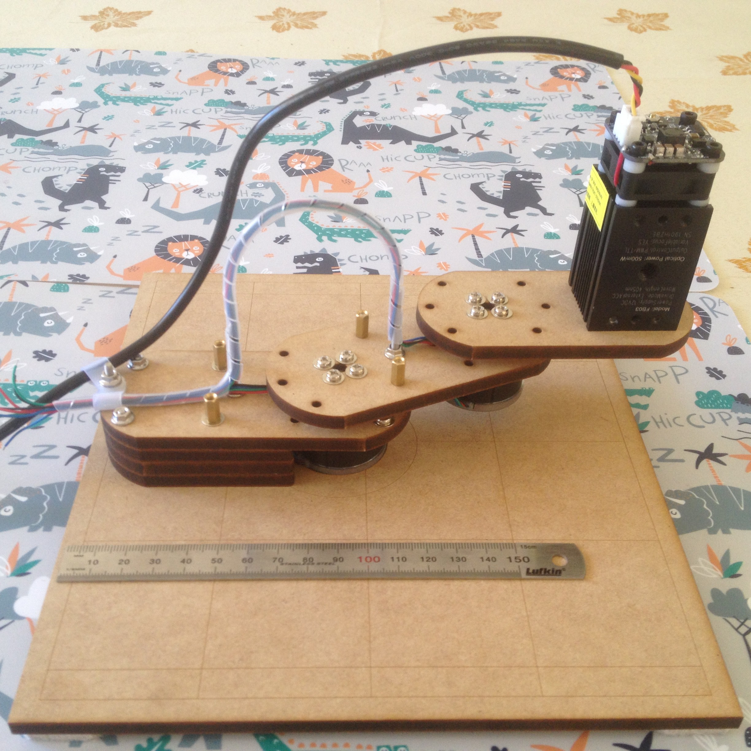
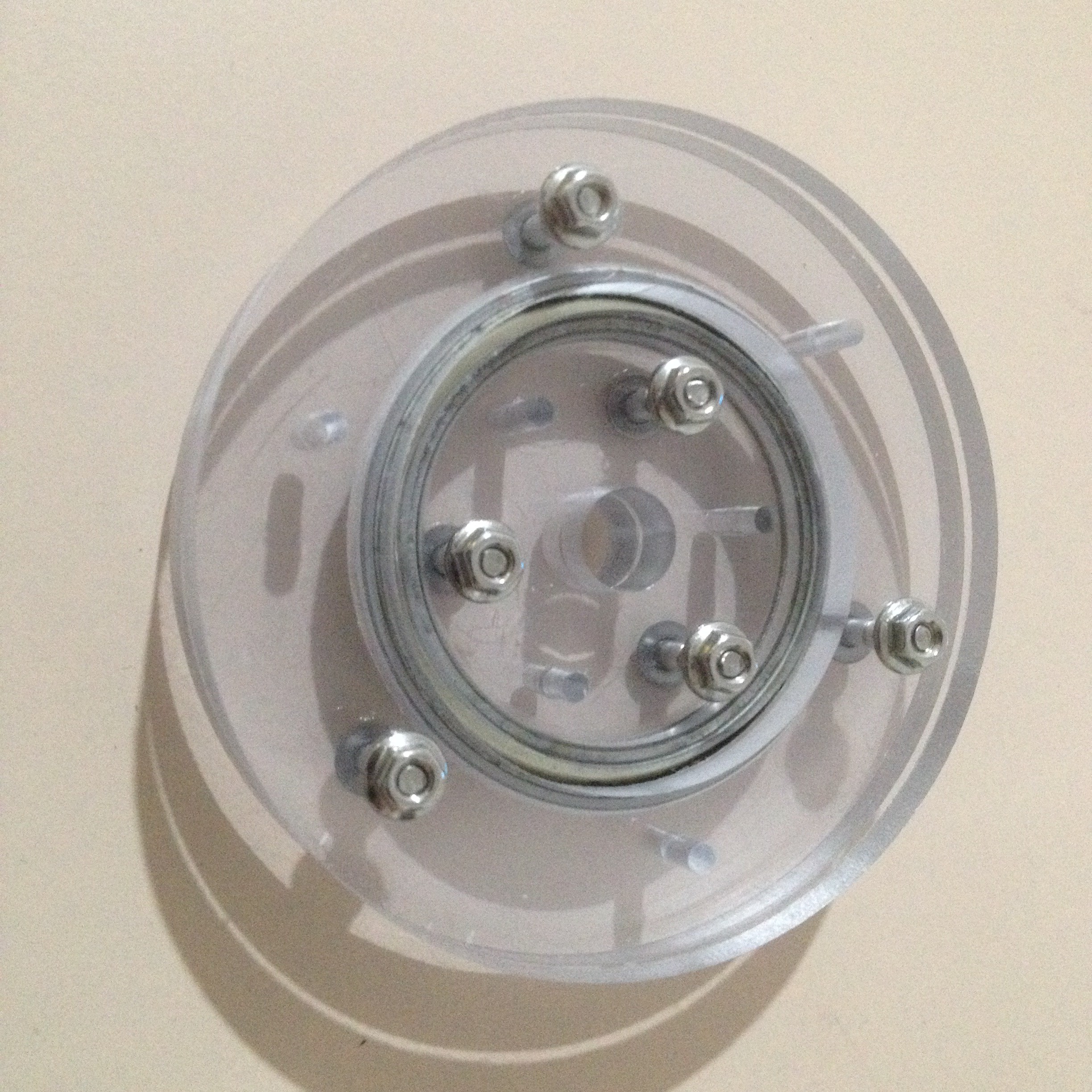
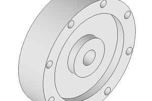
I need a slew ring for my next SCARA prototype, as it will be geared. Here is the first prototype. which is direct drive:
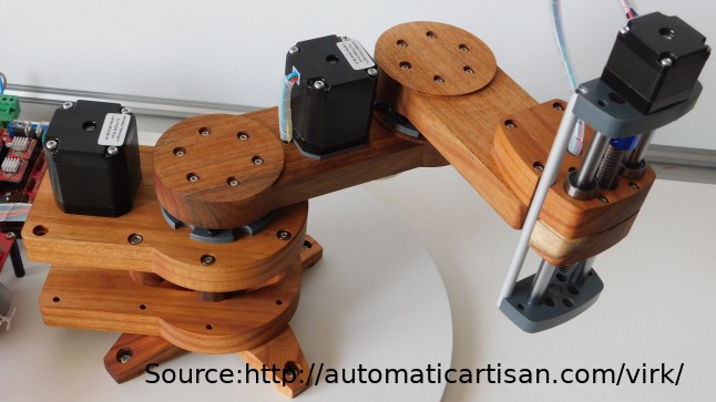
And this is what I want to be when I grow up:
What is with 2.5D
I don't have a 3D printer so I have to work with 2D (i.e a laser cutter) or 2.5D (i.e. a 3 axis CNC mill). This puts restrictions on what can be made (i.e. the design process).
It is not really practical to use very small end mills (i.e. 1 mm or less) on my CNC machine, they break too easily. This limits the design resolution (i.e. you cannot cut very fine gear teeth). And you cannot design concave surfaces on a laser cutter.
Commercial Offerings
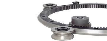
A quick look on Google pulls up the following (typical) designs that could be used as a basis for a DIY slew ring:
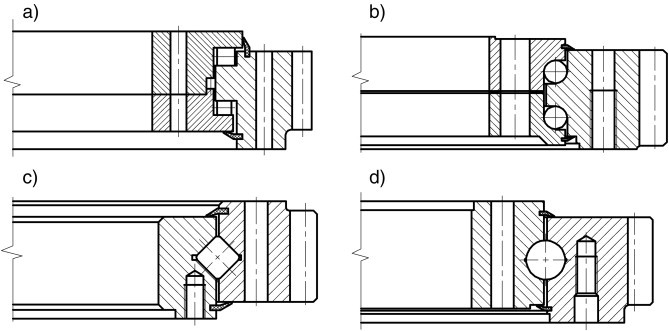
From a 2.5D point of view, design (a) and (b) look like candidates.
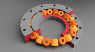
Others designs include:
Existing 2.5D DIY designs
This one is quite good:
Other Types
Why not a bicycle hub:
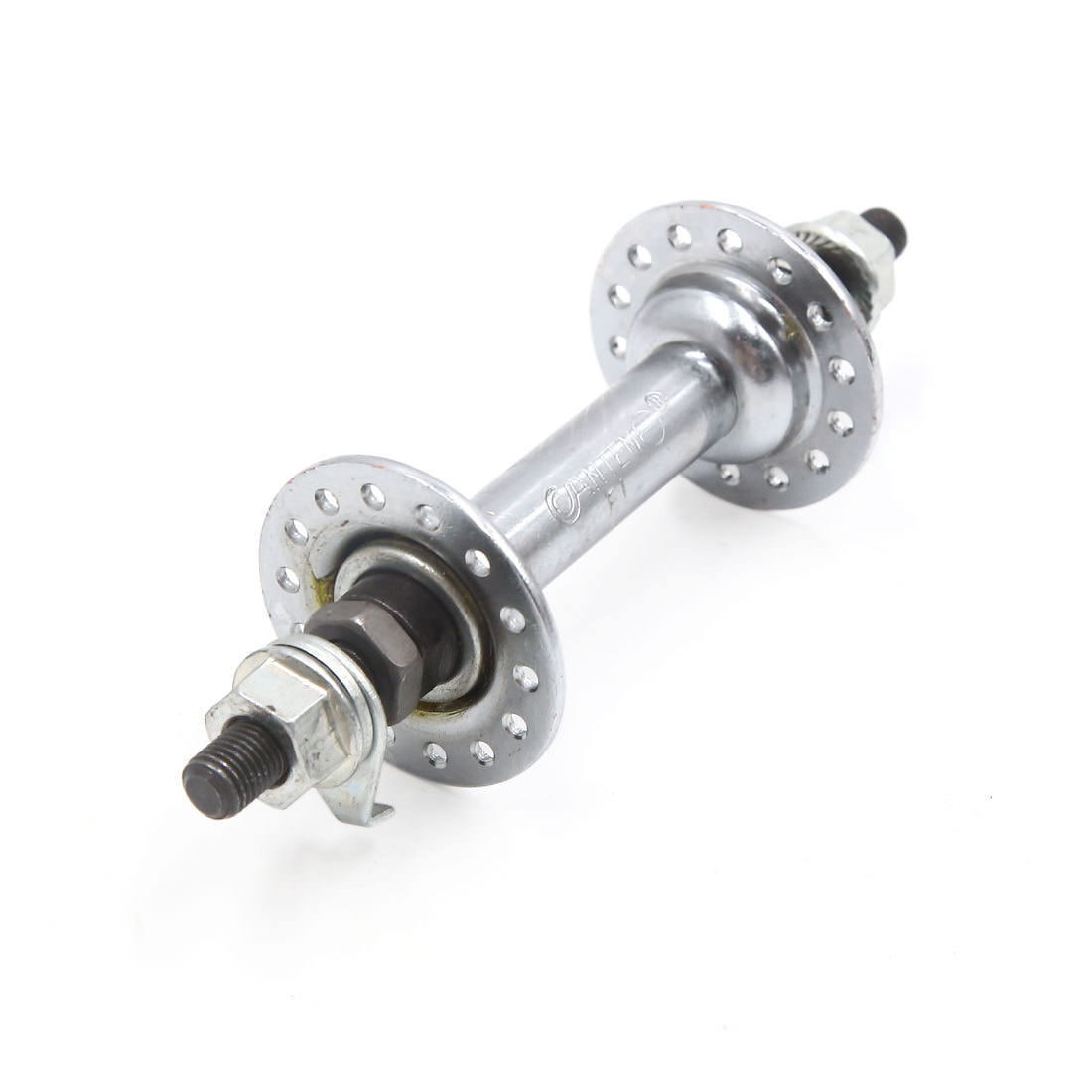
Now most SCARA 3D printed bearings are basically this type.
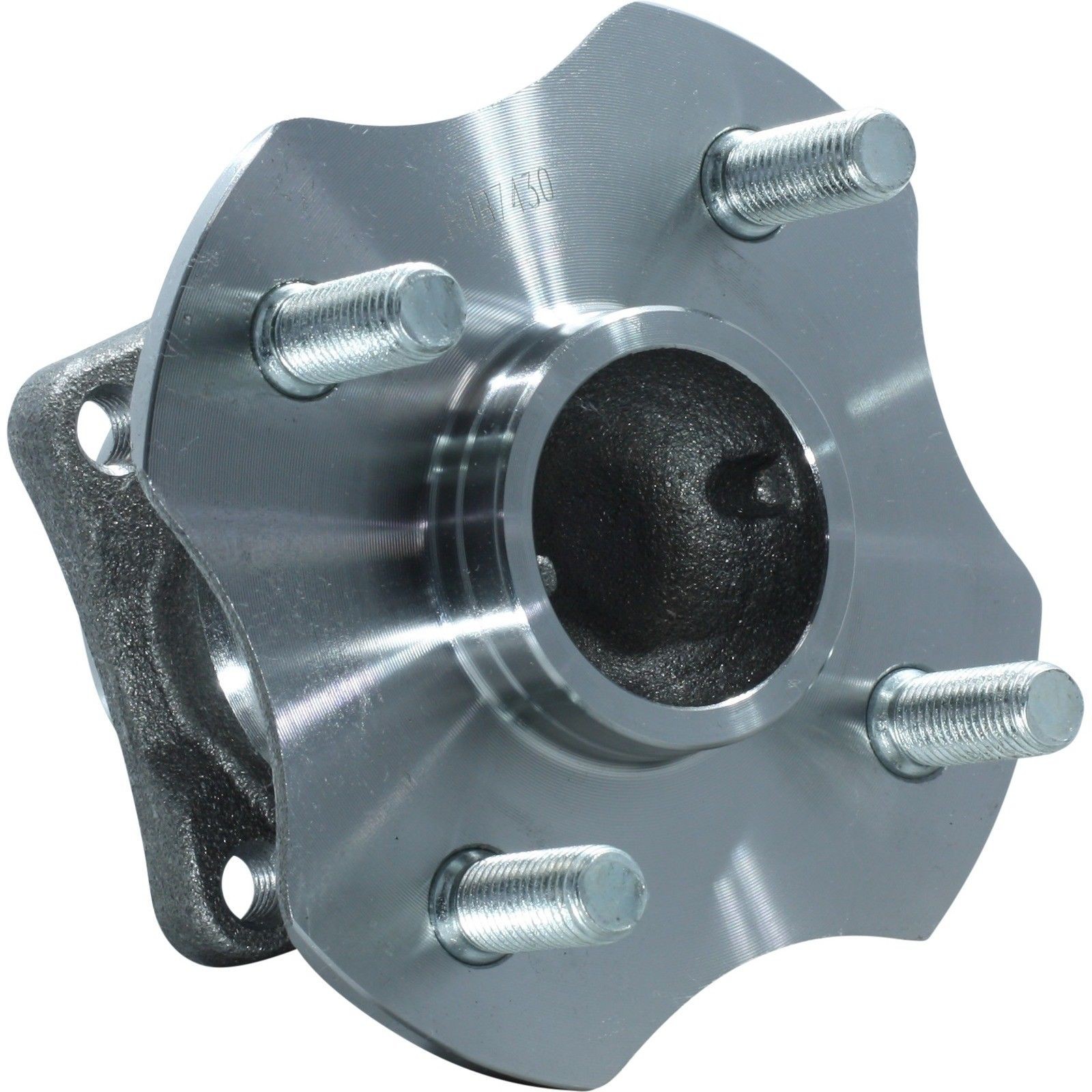
And finally, if you what to build a big SCARA, why not a wheel hub:
Using Existing Roller Bearings
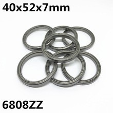
This project is about using an commercial roller bearings.
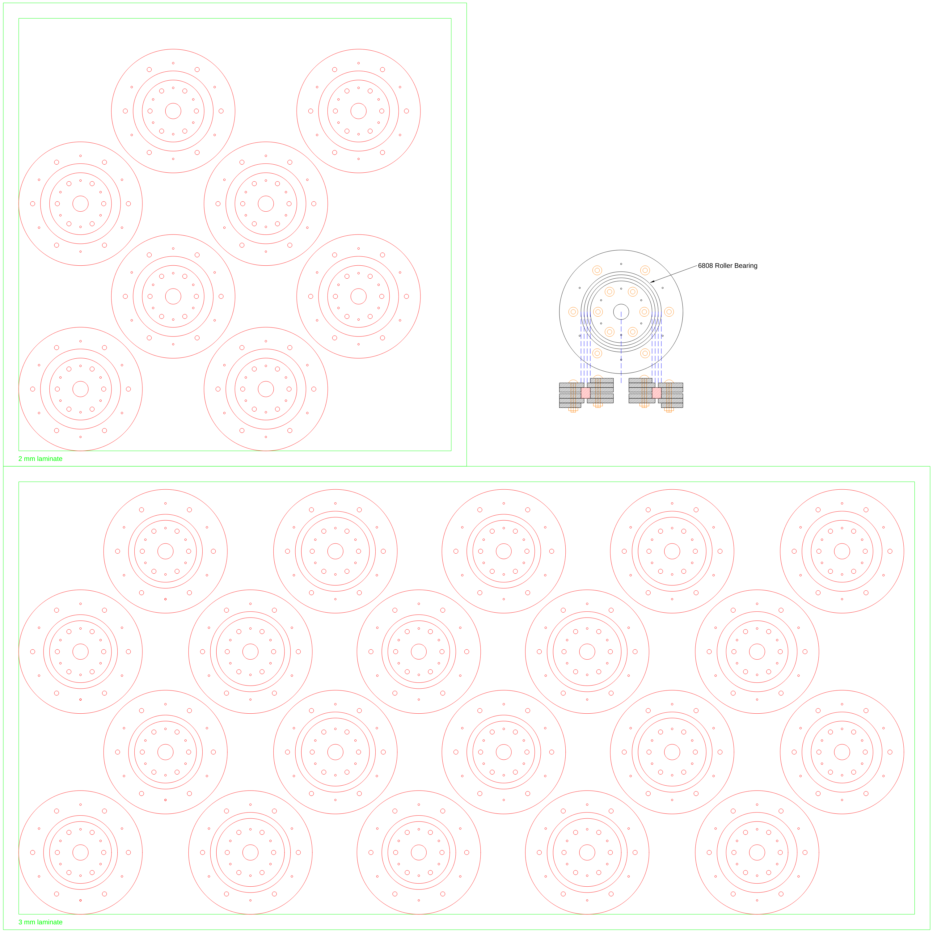
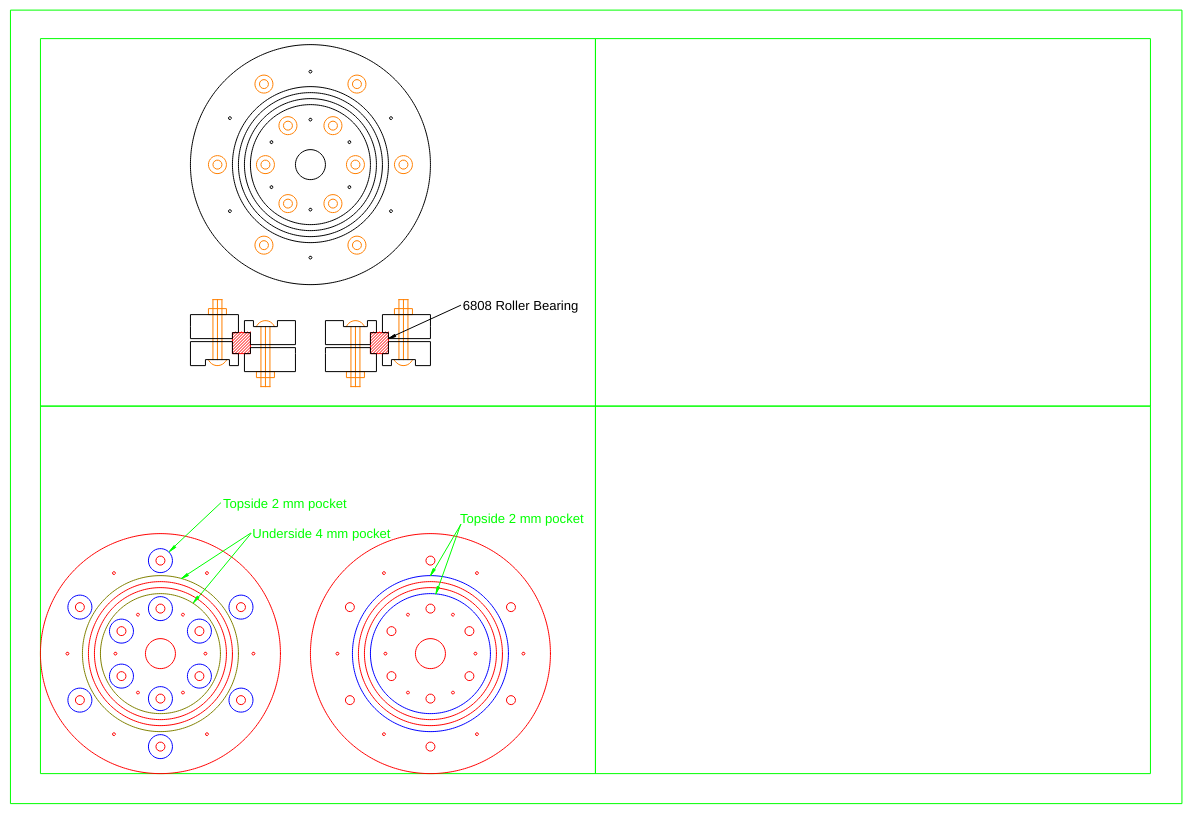
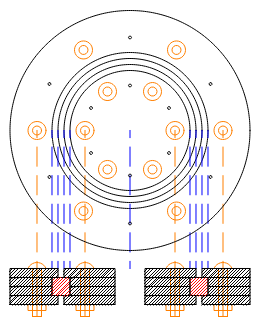
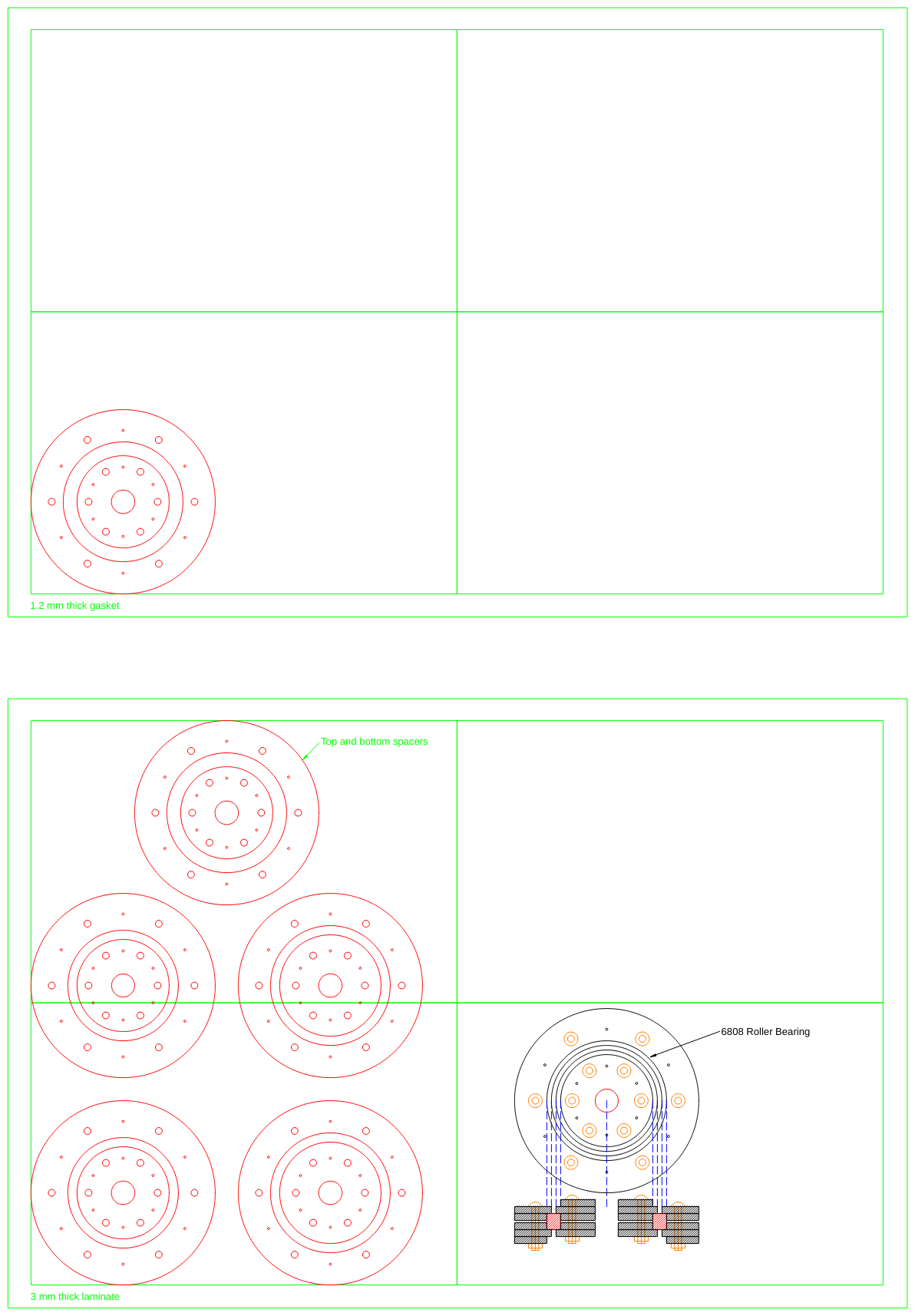
I bought a number of different sizes but most of them where pretty "sloppy". But the biggest I got (the 6808Z) was great:
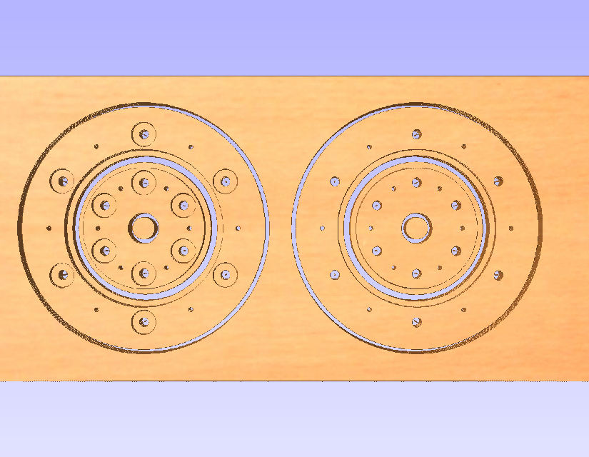
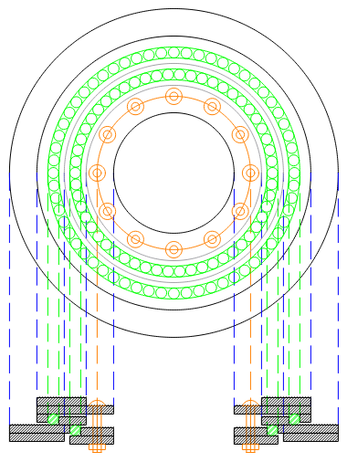
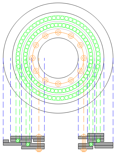
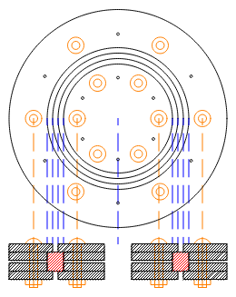
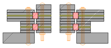
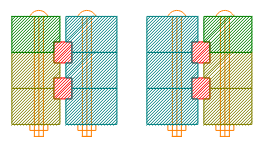
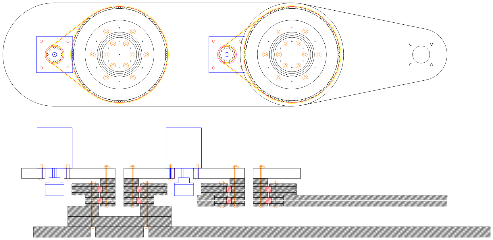
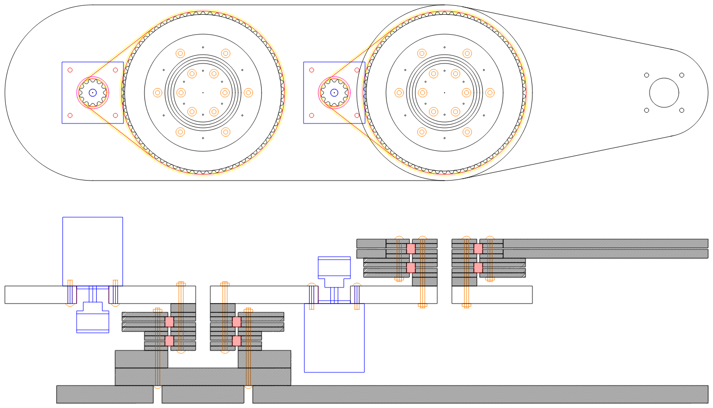
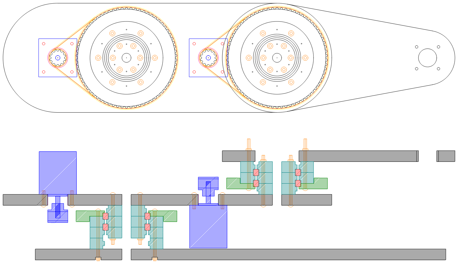
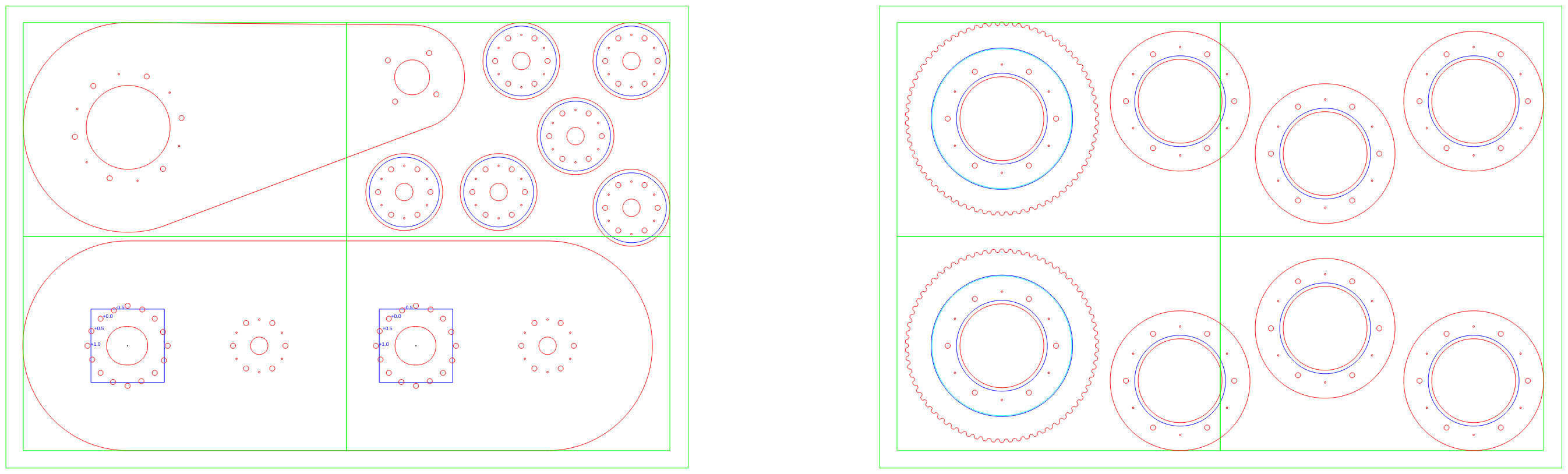
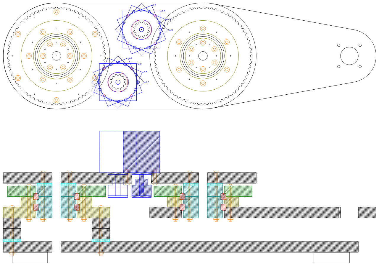
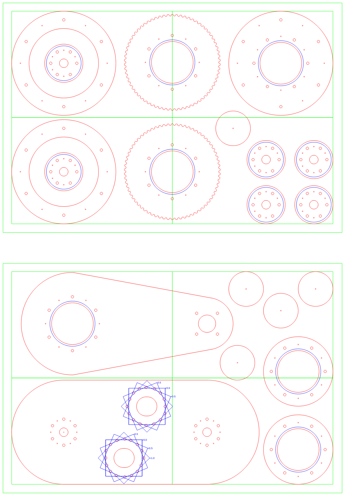
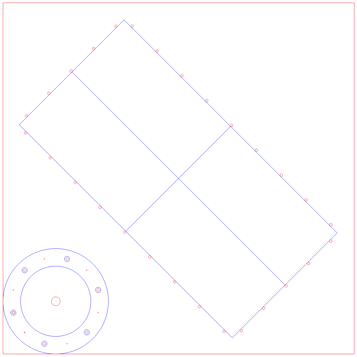
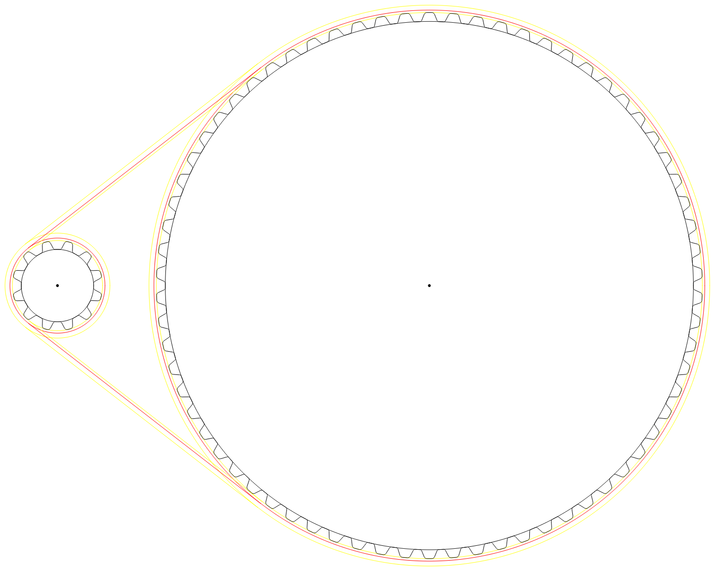
And here is the initial 2D design I cam up with:
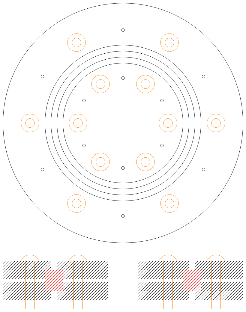
For this design the layers are 3 mm thick and shown as a 2D (i.e. laser cut design). Not hard to convert this to 2.5D (3 axis CNC mill).
AlanX


 Greg Duckworth
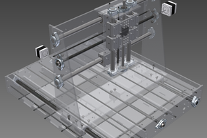
 Kert
Kert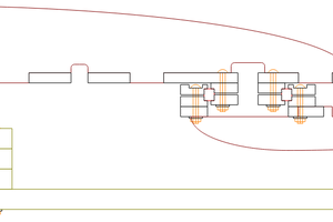

If you're using roller bearings, maybe try to use two bearings per joint with both sides of each inner race and at least one side of each outer race captured (something pre-loaded against it). If you just want to use one less expensive bearing, perhaps use a four-point bearing and be careful to capture as many of the sides of the bearing races as you can.