 alessandro verdiesen
Hand-detection
The sensor is realized with the reflection of infrared light photons. The sensor contains infrared transmitting and infrared receiving LEDs. These will be named as sender and receiver from now on.
There are serval things that are being kept in mind during the development of the sensors:
- The sensor must not interfere with other sensors. This means that the light from the adjacent sensor should not be picked up with reflection from the next plane.
- The sensor can detect objects to approximately 30cm (≈ 11,8 inch).
- The signal has an analogue output. The sensor will be designed so expansion in later upgrades are possible.
The circuit is designed so it can operate at 5 Volts because the hardware (Arduino, Raspberry and amplifier) also operate at this voltage.
Transmitter
For the transmitting LEDs, it is important that they all have the same transmitting power. We decided that LEDs will flash with a frequency of around 7 kHz. With this frequency, other sources (e.g. sunlight, 50Hz grid lighting) will not cause any interference. The LEDs have a wavelength of 940nm. The LEDs will be controlled with an interrupt on the Arduino board.
Receiver
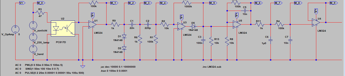
The receiver uses a quad opamp as main part. With reflection of the infrared light on a hand or object, a photodiode will conduct. This conductance is then used to create a voltage on the output of the first opamp.
We used LT-spice to simulate the infrared light that is reflected on a hand or object. A photocoupler is used to simulate the transmitting and receiving part of the circuit. This is a diode and a transistor that can simulate the transfer of infrared photons. The number of photons transferred from the diode to the receiver ensures that the receiver is 'opened'. The photocoupler is indicated with U2 in the circuit.
M0 Input:
This first image shows the voltage of the simulated transmitter with distortion from other sources.
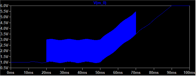
The 50Hz grid distortion begins at 10ms. This is followed by a simulated object in from of the sensor. After 50ms the simulated sunlight comes in.
M1 and M2:
The photodiode starts conducting with incoming IR light. This conductance then will create a voltage on the output of the opamp. (Vout = -Iph * Rf)( non-inverting amplifier)
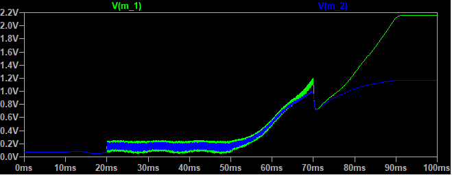
The photodiode draws a certain current(uA) from the opamp. Because opamps have a very high input resistance, all of the current comes from the output. The amount of current, or in this situation infrared light intensity, will create a voltage. This voltage is then filtered for measurement later in the circuit.
In order not to let the final stage clip too fast, two diodes are placed on the output. The voltage after these two diodes will not be higher than 1.4 Volt.
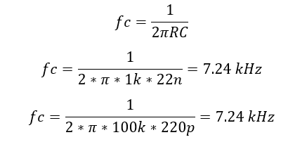
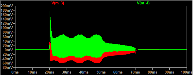
M3 and M4:
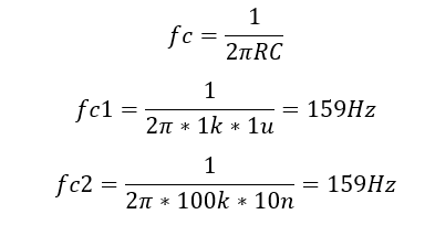
Two high-pass filters are placed after the second stage for filtering sunlight. The filters are connected in series to become a second order RC filter.
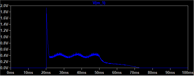
M5:
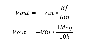
In this part of the circuit, the filtered signal is amplified in the positive side only. Because there is a diode in the feedback, the opamp will obstruct all negative voltages from the two high-pass filters. This is an inverted amplifier.
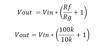
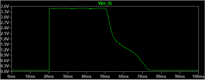
M6:
The voltage measured at the M5 point is quite low. This ensures that the ADC in the Arduino won’t reach his full range. This is why we’ve added an amplifier at the end of the circuit. There’s also a low-pass filter in this amplifier. This filter will flatten the signal so that the analog output fluctuates less.
M7 and M8:
Then the signal is filtered even further. In practice the measurement at point M6 still fluctuated too much with the movement of hands playing the Airdrum. Two low-pass filters are placed in series for the filtering of this signal.
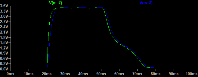
As the last stage, an opamp is used as a buffer. This is done because there’s one left in the quad configuration of the opamp and it also ensures a stable signal regarding what is used as a load on the output of the sensor panel.
Discussions
Become a Hackaday.io Member
Create an account to leave a comment. Already have an account? Log In.