 Tim Wilkinson
-
It's alive!
05/23/2019 at 17:38 • 0 commentsDetails to come ...
-
AS5047 Encoder Placement
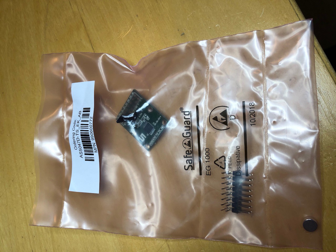
05/23/2019 at 05:00 • 4 commentsFor accurate control of the joint, ODrive requires an encoder. There are many options here, but I wanted something as lightweight and small as possible. Without the need to write a new device driver, ODrive supports encoders using the ABI format so I picked out a magnetic encoder; the AS5047 (in retrospect, I should probably have gone with the AS5147 which has better resolution). This is a single chip encoder which relies on a spinning magnet, attached to the motor shaft, to monitor the motor position.
![]()
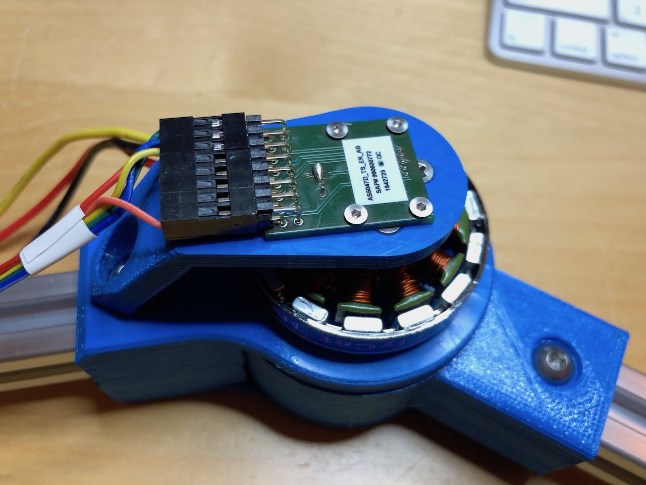
Attaching the magnet to the motor shaft was a bit of a pain. I tried a couple of epoxies and 3d-printed jig setups before I found something which would center the magnet well and keep it stuck in place - JB Weld for the glue and a two part jig which snuggly held the magnet in place on the motor shaft while the glue dried.
Once the magnet was stuck, the AS5047 board was mounted, face down, above it. I cut down the 3.3V/5V selector and hard-wired it to 5V (see the unsightly solder blob).
![]()
With everything assembled I now need to run though the ODrive configuration and calibration process.
-
PET vs PLA
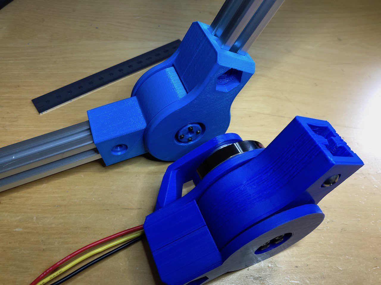
05/21/2019 at 21:36 • 0 comments![]() Perhaps unsurprisingly, the joint printed in PET (light blue) is much smoother than the joint printed in PLA (dark blue) - and the blue PET PRO from Matterhackers is rather nice. I've mostly been prototyping in PLA because is easy to use, but it clearly wears quickly and heats up when testing (and PLA doesn't do well when it gets hot). The joint is also easier to back drive, which is a property I hope to use to measure the load on the motor in order to provide compliance.
Perhaps unsurprisingly, the joint printed in PET (light blue) is much smoother than the joint printed in PLA (dark blue) - and the blue PET PRO from Matterhackers is rather nice. I've mostly been prototyping in PLA because is easy to use, but it clearly wears quickly and heats up when testing (and PLA doesn't do well when it gets hot). The joint is also easier to back drive, which is a property I hope to use to measure the load on the motor in order to provide compliance.I'm still tweaking the dimensions of the various parts for the best compromise of fit and tolerance - it's something to obsess over while I wait for the position encoders to turn up.
-
Cycloidal Drive
05/20/2019 at 18:08 • 1 commentBefore reading anything else, go and checkout this excellent project by Paul Gould. His work was very inspriational. In fact, before stumbling on this I'd never heard of a Cycloidal Drive. I'd been looking for a way to rework my stalled robot arm project as I'd been unsatisfied with the design. However, I'd not found a practical way to build a large gear reduction in a small space using planetary gears. Paul's work showed me there was another way.
I wanted to impose a few more constraints on my drive; specifically I didn't want to modify any of the purchased components and generally wanted to simplify, and reduce the costs of his design. So no custom PCBs or motor mods for me.
I designed the drive around a cheap, low kV motor, from Amazon which cost about $22. How well going cheap will work out only time will tell, but for my limited tests so far thes motors have been great. The drive would then provide a 32:1 reduction and result in a joint which is both sufficiently torque-y as well as being fast.
The drive was prototyped in PLA. I don't recommend PLA as a final material (some PETG should arrive today so I can re-print) but it's sufficiently forgiving for prototyping. And I did *a lot* of prototyping - I have a modest sized bucket of rejected parts.
There were two big problems I had to solve while designing this, and one of them was my own inability to understand what I was doing :-) Seriously, it took me ages to realize that the two cycloidal disks in the drive (you need two because each one is eccentrically mounted and requires the other to offset the eccentric momentum) needed to be offset by half-a-tooth.
The second problem was my attempts to be cheap (again). I wanted to keep the number of bearings used in the design to the absolute minimum. The two bearings to allows the eccentric motion of the cycloidal disks are unavoidable, but perhaps I could skim on the others? After all, the motor provides a bearing at one end of the input, and maybe I just needed one on the output? In practice, so long as you don't actually put a load on the drive, this worked fine. However, once any significant load was applied, the parts quickly become mis-aligned - just a tiny bit - and everything locked up. So the final design has two 6808 bearings supporting the output, two 6803 bearings supporting the input, and two 6803 bearings for the cycloidal disks. Disappointing, but works solidly under load.
The final design can be seen here (I've omitted the bearings for clarity). I'll run though the details of the design in another post.
-
ODrive
05/19/2019 at 18:39 • 0 commentsIf you're not aware of the ODrive then check out the Hackaday page here and their website here. The ODrive is designed to turn hobby brushless motors into accurate robotic actuators. As their creator Oskar says, such a controller should clearly exist but since it didn't, he built one.
From my perspective this device is idea because it's open source and I intend to modify its firmware in order to support joint compliance. Right now ODrive operates as a traditional rigid controller, moving either to a specific position or at a specific velocity without regard to load or resistance. I intend to add to these control mechanisms so joints can act with elasticity.
Imagine pressure on a robot knee compressing the joint slightly as it holds the robot weight. There are a number of ways to achieve this. The passive way is to add springs or elastics to the join so they flex under load. Alternatively, we can simulate this (with Hooke's Law) by detecting the load on the joint and actively adjusting the joint position. Well, that's the theory anyway, and there are many examples of this technique in high end robots, but nothing hobby level that I could find.
So here we go, but first to get the joint built and operational.
3D Printed Robot Joint with Active Compliance
A general purpose robot joint using a cycloidal gearbox and an ODrive modified to support active compliance
 Perhaps unsurprisingly, the joint printed in PET (light blue) is much smoother than the joint printed in PLA (dark blue) - and the blue PET PRO from Matterhackers is rather nice. I've mostly been prototyping in PLA because is easy to use, but it clearly wears quickly and heats up when testing (and PLA doesn't do well when it gets hot). The joint is also easier to back drive, which is a property I hope to use to measure the load on the motor in order to provide compliance.