FuzzyNoodle
When I am building a biped robot, I was always thinking of having some sort of cool gadget that can trace my opponent and do attack moves with it. Bunches of radar/lidar projects already exist here. However, there are some limitations for my purpose:
- Ultrasonic wave sensor modules are quite large. Every robot would look like WALL-E.
- Current radar projects all includes a sensor (either ultrasonic waves, IR, laser, ...), and a servo motor in the middle. Scanning the environment requires the servo to move side to side. Moving stuff back and forth creates momentum changes, which is bad for biped balancing and walking.
- Scanning frequency is limited by servo speed. Only several hertz can achieved, probably. Even if the scanning frequency can be ramped up by some super-servo, this would result in heavy vibration.
- [Central servo motor - sensor] arrangement also limits the position for mounting and the design. It is difficult to mount such thing other than as a head. Which makes my biped look like a shaking-head WALL-E every time. Not cool!
- The [servo-sensor] arrangement can also be built as a [motor-sensor] style. The sensor (or sensors) is rotating along a motor axis continuously. This may eliminates the momentum jerks and low scanning frequency problems, but not the torso design limitation. Wiring difficulty would also increase substantially.
After searching, this tiny sensor VL53L0X from ST splashed into my eyes. By claiming "World Smallest" time-of-flight ranging sensor, the dimension is only 4.4 x 2.4 x 1.0 mm. Featuring
- On chip IR laser emitter and detector
- Up to 2m range (1.2m in fast mode)
- Programmable I2C address
- A GPIO interrupt output pin
- Eye safe
All these special features combined enabled me to overcome the problems above, if an array of VL53L0X sensors could work. Originally, I thought this radar would be called solid state radar, but found out that this term was used for something else. Therefore the "Stationary" word in the title means that there are no moving parts in this radar gadget. Also, while LIDAR (light detection and ranging) is the technically correct term for this chip, RADAR is referred here as a more generic term.
The reason why Programmable I2C address and GPIO output pin are critical to this project is explained later.
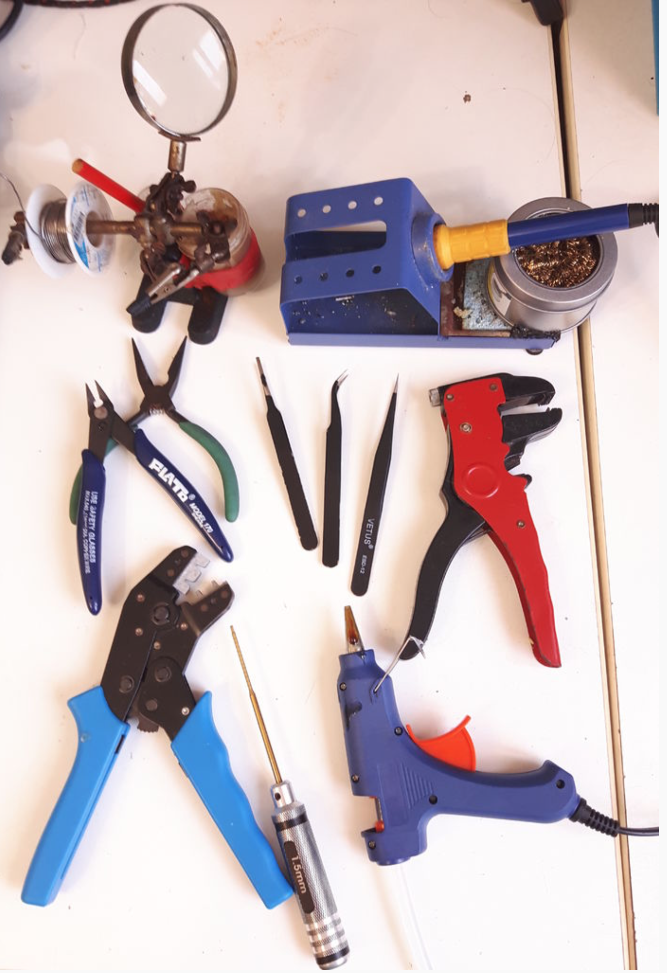
Tools
The following tools are required in this project:
- Soldering iron
- Soldering helping hands
- Dupont crimp tool
- 1.5mm hex driver
- Wire coating removal tool
- Wire cutter
- Hot glue gun
- Tweezers
- Magnifier (physical or apps in your phone)
- Flat nose pliers
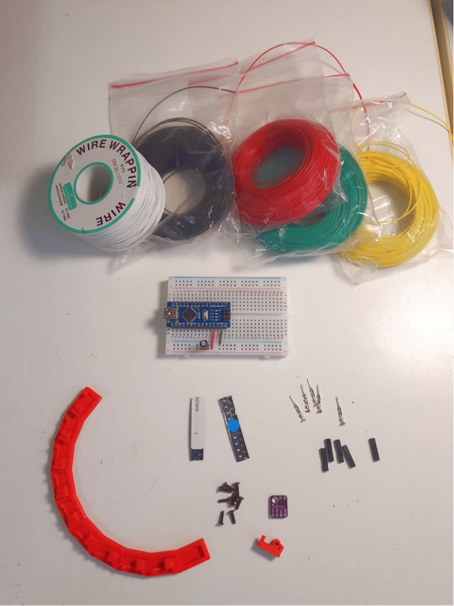
Parts
The following parts are used in this project:
- 10x VL53L0X GY-530 breakout boards
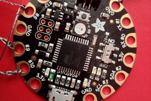
- An Arduino (Uno, Nano, Mega, Zero, Mini, ...etc)
- A breadboard and some breadboard wires
- AWG #26 wires with different colors
- AWG #30 single core wire
- 5x Dupont male connectors
- 5x Single pin Dupont housings
- 10x 3D printed breakout board holders
- 1x 3D printed circular frame
- 10x M2x10 flat head screws
- 10x 0804 LED(Blue reommended)
- 10x SOT-23 AO3400 N-Channel MOSFET
- A small capacitor (10~100uF)
Breakout board
The VL53L0X breakout board I used is GY-530. There are also Adafruit version and Pololu version available. If feasible, I do recommend using Adafruit or Pololu's product because they make great products, great tutorials, and great software libraries. I tested on Adafruit's VL53L0X library and used a modified version of Pololu's VL53L0X library.
Dupont connectors
The dupont connectors are used for the breadboard. You may use any other types of connection you have in hand.
Screws and 3D Printed Parts
The M2 screws, holders and circular frame are used to place the sensors in a circular arrangement. You may use any other methods, such as using...
Read more »
 Christoph Tack
 Thomas Snow
 jean.perardel