 Boris Landoni
The project
The shield creates the interface between Randa and the electromechanical part of the machine.
Based on RandA, this machine can prepare cocktails, by drawing the quantities from dedicated dispensers, according to recipes dowloaded from the webpage from which the drink has been requested.
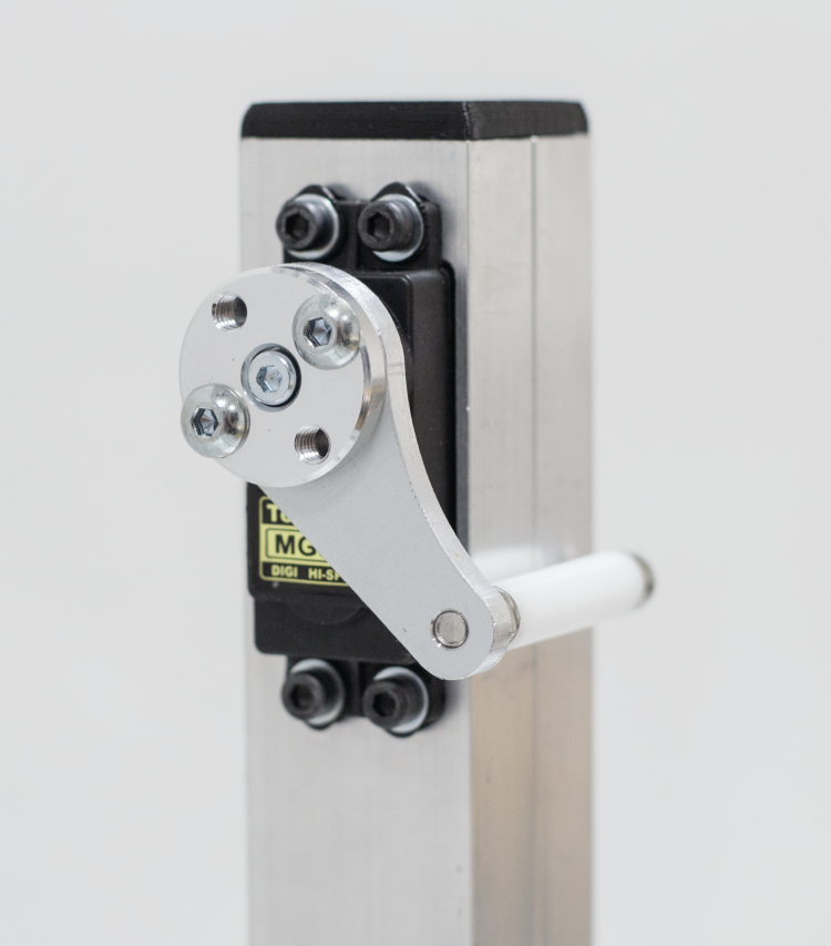
Our robotized drink-making machine is a chassis composed by aluminium extrusions, upon which dispensers are applied in a row: they are activated by a rear button, pressed by a lever commanded by a servomotor. Each time it is activated, each dispenser supplies a predetermined drink quantity, in our case corresponding to 2 cc (20 ml). Each dispenser is mounted upon a bottle carrier, that allows the insertion of the nozzle as gasket in the bottle neck, so to give stability to the whole.
The whole stays on the machine’s raised part, fixed at the base on which the mug holder cart runs on the axis in a linear way. It runs by means of some ball casters on the cavities of the aluminium extrusions, that are longer than the chassis. Behind the cart a servo control that activates the dispenser is fixed as well, thus each time the cart brings the glass under a dispenser, this last one is activated and pours his dose for the number of times set by the system. To avoid that the cocktail is shaked up to the point of pouring the fluids out of the glass, during the passage from a dispenser to the other one, we saw that the cart’s speed changes in a progressive way, by starting out slow to reach the top speed after about a second, and then to slow down up to the point of stopping, after another second. The cart’s movement is achieved by means of a dented belt that bites a pulley (also dented), and activated by a stepper motor placed on the inferior part of the chassis. The motor is managed by a dedicated controller and lined to the start on the basis of a limit switch that has been placed all to the left, and that is stimulated by a specific protrusion of the cart. The beginning of the course corresponds to the first dispenser, thus during the building phase of the machine you have to make sure to place the limit switch so that its lever is pressed when the cart has the glass centered in respect to the first despenser’s nozzle.
In order to make it possible for the mechanics to carry out what has just been described (that is to say to bring the cart with the glass under the bottles needed to prepare the required cocktail, and to receive from the dispenser the drink quantity that has been indicated), a quite refined electronic control is needed. In our case, this is achieved by combining Raspberry Pi, our RandA board (a bridge between Raspberry Pi and Arduino), a specific shield and a motors driver, and in the end this is the same that has been used for the 3D 3Drag printer’s project. The whole sequence of the movements needed to prepare a cocktail and to bring the glass containing it back (to the beginning of the machine so that it can be picked up), is decided on the basis of the composition of the cocktail itself. This one is chosen by the user by means of a customizable web interface. Thus we have a part of the electronics that enables us to choose the cocktail from a database (previously prepared by the system manager and that can be composed at leisure). Another one translates the ingredients of the cocktail itself in mechanical movements (moving the cart, pressing the dispenser’s button…). Finally, another part physically controls – by following the corresponding instructions – the step by step motor and the servo control to operate the appropriate actions.

The entire electronics takes place in the container printable 3D, to be fixed to the side of the frame and from which come the cables and connections of Raspberry Pi.
In particular, in the electronic section of the machine:
- Raspberry Pi generates and governs the user web interface, works as a host for the cocktails’ settings, manages the auxiliary functions such as verifying that the order can be satisfied on the basis of the ingredients available that compose the cocktail (it keeps memory of the quantities that have been distributed, it notices the capacity of the bottle for each dispenser). Thus, for each product it prepares the series of commands for positioning and for the dispenser’s button activation, that will then pass on to the Arduino’s section;
- RandA, that contains Arduino Uno’s hardware and the interconnections with Raspberry Pi. It receives from the latter the instructions concerning the preparation of the ongoing cocktail, that is to say the position required and the command for the dispenser’s opening button, and converts them into direct commands to the motor and servo control, then gives appropriate commands as an appropriate sequence;
- the shield interfaces the RandA board with the connections of the stepper-motor and of the servo control, with the signalling devices (we will talk about them soon), with the limit switch and more, in addition to hosting the motor driver;
- the motor driver, on the basis of the impulses received from RandA, drives the stepper motor to make it advance for the number of steps required.
More exactly, in its firmware RandA has written the relationship between the advancement needed to reach each dispenser and the corresponding number of paces that the stepper-motor has to take. For example, in the machine we created for the tests the distance between a dispenser and the following one is 97,7 mm; and the distance from the beginning of the course to the first dispenser is zero. Translating this in terms of steps, it means that the first dispenser corresponds to the starting position (thus to draw the content of the bottle therein applied you just need to command the servo that activates the button, without ordering any advancement for the cart). On the other hand, to reach the second dispenser from the first, RandA has to send 6.300 impulses to the controller, corresponding to 6.300/16 steps (because the driver is set so to execute a complete step every 16 impulses) that the step-by-step motor will have to take. The distance between dispensers, that is to say 97,7 mm, thus corresponds to 6.300/16 paces of the stepper-motor (1 step enables to travel 0,248 mm).
Thus, when it receives the order to reach the first dispenser, it translates it into motor steps and sends the number of impulses corresponding to the control lines of the motor driver, so that it may activate the stepper-motor. Once the indicated number of paces has been completed, RandA will give the order for the activation of the servomotor, that presses the button of the dispenser under which the cart was brought. Once the sequence for the positioning and dispenser‘s opening has been completed, the cart is brought back to the beginning of the course to serve the cocktail. The stop happens when the limit switch is activated, as soon as the system ends the sequence and the execution of a new order is prepared.
That’s all as regards the activation; a part that we might call a “choreographic” one has also been taken into account, as well as one for the optic signalling, as assistance for the “bartender on duty”. A LED strip based on the Philips HL1606 controller, with the lights that can be managed by SPI serial bus, is commanded by means of the shield, so to create pseudorandom lights in order to embellish the machine. At the beginning of the cocktail’s preparation sequence, however, it will flash and show a light bar that shortens itself in 10 seconds, thus indicating the time left to put the empty glass on the cart, before the preparation starts. If the glass is not put there in time, unless the process is stopped by pressing the reset button on RandA, the machine will go on and pour the content drawn from the dispensers on the bottom of the machine… And this is not good, since the wiring or the stepper motor or the limit switch can get wet.

The strip of LEDs is provided with a connector to 2,54 mm pitch and takes power from a female jack wheel.
Shield’s electrical diagram

The shield carries all the connections to the machine and receives the power supply for the motor and the LED ring. The fan is mounted on the plastic container.
The circuit that interfaces RandA with the machine’s mechanics is contained in a shield on which the motor driver is mounted (for its description we refer the reader to the dedicated diagram in these pages). The shield hosts the basic connectors for the application, such as the one to connect the limit switch (STOP contacts), the LED strip (STRIP contacts), the servo control (SERVO) and a possible contact with which to subordinate the order (for example, it is applied at the output of an electromechanical token dispenser, with free contact normally open) whose connector is signed GETTON. The auxiliary connectors (CND3, CND8 e CND11, which have been reserved to possible developments: if you feel like doing it, you can do by yourself) have been prepared. The LED connector is there as well, to light the decorative LEDs to be arranged under the glass housing, so to create a play of the light. The limit switch can be NC or NO, connected between S and the positive or between S and the ground, but in our application it is NC, connected between S and ground. For this purpose, the RandA firmware sets up the internal pull-up resistor for the corresponding line (Arduino’s A3), so that when the switch is idle and closed, RandA’s ATmega receives the logical zero, while when the idle position is reached, A3 is at logical 1. The choice to use a NC switch has been imposed by the fact that the machine stops the cart and the sequence by opening it, thus if a wire is cut or detached, we are certain that the machine will stop.
The software
Having ended with the hardware analysis, we may devote some time to the project’s software. Essentially, it takes into account the software to be loaded in RandA, and the actual software, that will take place and run in Raspberry Pi. This program consists of a database and a user interface, that is divided in two parts:
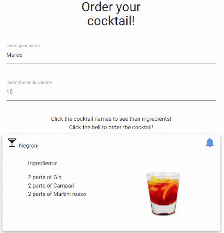
- a front-end, built from the web-page that the user may see, by pointing Raspberry Pi’s IP address, and on which it operates so to make orders;
- a back-end (admin), managed by the system administrator and invisible to the user.
In turn, the Admin part is divided in three parts:
- one of them shows the cocktails being prepared, and the queue processing them (name and cocktail name, plus current state: for example it may be in the “making” phase –that is to say the cocktail making sequence has been started- or approved, that is to say the cocktail has been “approved”, since the ingredients are available);
- ingredients; select which bottles are filled, which parts (each one being 2 cl) does it contain, the slot (dispenser) position and the possibility to add more ingredients;
- cocktail composition (parts, name, possibly a picture to help the user when choosing, etc.).
The user selects the cocktail on the web interface, managed by Raspberry Pi. This last one processes the order and verifies if it is possible to make it (depending on the availability of the ingredients and also considering possible orders queued). Afterwards, if everything is ok, it will pass to Arduino the data concerning the cart’s position and the number of drink parts to be taken from each one. Arduino simply controls the stepper-motor, in order to move the cart; and the servo, in order to activate the dispenser.
The LED bar, once the procedure is started, indicates with this sort of countdown bar that we have about 10 seconds to place the glass. After that, the machine goes on with the sequence.
As regards RandA, the firmware running on it simply serves the purpose to interface Raspberry Pi, and to convert its requests into orders destined to the servo control’s activation and to the stepper-motor’s movement.
As for the servo’s management, a dedicated integrated library (found within the sketch) is used. Similarly, for the strip management there is an Arduino library for the management of the Serial Peripheral Interface (SPI) interface, with or without Latch and Sync lines.
The LED ring’s management is also transferred to a specific library, made available by Adafruit, that is the ring’s manufacturer.
Enjoy a nice ice-cold cocktail