 Jan
JanA few notes on this board, which can be used in various configurations:
- the XC6201P332 regulator can be left out: just use the 3V3 pins to feed the Attiny!
- you can use the full voltage range of the Attiny then, up to 5V5
- with the XC6201P332 regulator soldered you could feed 3V3 (up to 5V5) into the 3V3 rail, it does tolerate it but is not advised. Make sure to not have no voltage present at the V_in pin then!
- D1 + R1 are optional and just show you there's 3V3 present
- both 100n ceramic capacitors on the bottom of the board should be soldered
- the 100n + 10uH combination on the bottom can be omitted but is advised to solder on when you want to use the Attiny's ADC. It is a filter for more noise free ADC readings
- the 10uH can be substituted with a 47R resistor
 togorean.bogdan
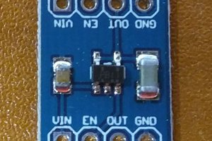
 Dave's Dev Lab
 Ben Lim
 Sean Hodgins
Hello Jan, have you got any empty PCB leftover ? Br Erik