 smartroad
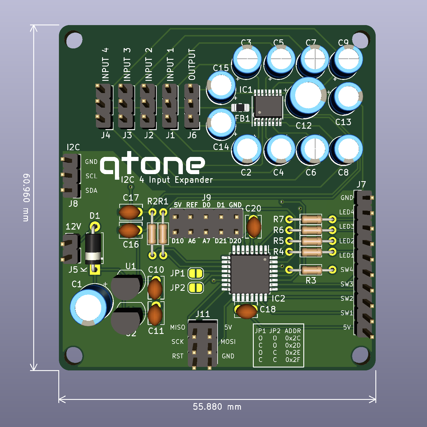
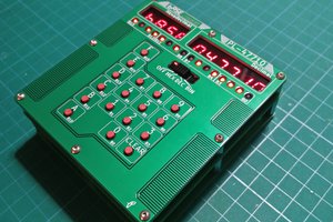
The project has been updated to use an ATMEGA328 to control the audio switch IC from either push buttons, rotary switch (1P4W) or I2C. It has been designed to integrate into my amplifier via I2C and can be controlled via that allowing the LCD display to be updated with the correct names and pre-amplifier amount. It doesn't need to be connected via the I2C and can be used by any amplifier using the push buttons or rotary switch.
0%
0%
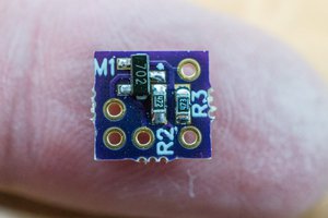
Audio Input Expander
Add 4 extra line level inputs to your amplifier
Become a Hackaday.io member
Already have an account? Log in.
Just one more thing
To make the experience fit your profile, pick a username and tell us what interests you.
Pick an awesome username
hackaday.io/
Your profile's URL: hackaday.io/username. Max 25 alphanumeric characters.
Pick a few interests
Projects that share your interests
People that share your interests
 Bud Bennett
 OzQube
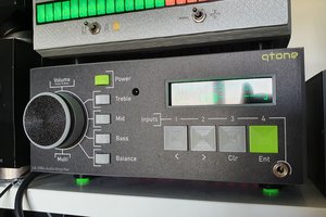
 leumasyerrp