 smartroad
Since completing the PCB and building the first version I have further updated the circuit. For some reason I had put in the crystal oscillator for the ATMEGA. I have no idea why because it was always going to be driven by the internal RC oscillator, mostly as it doesn't have any specific need to accurate timing and the I2C bus is clocked so again is independent of the ATMEGA's clock. I am using MCUdude's MiniCore and with the RC OSC in use the XTAL pins can become additional IO pins.
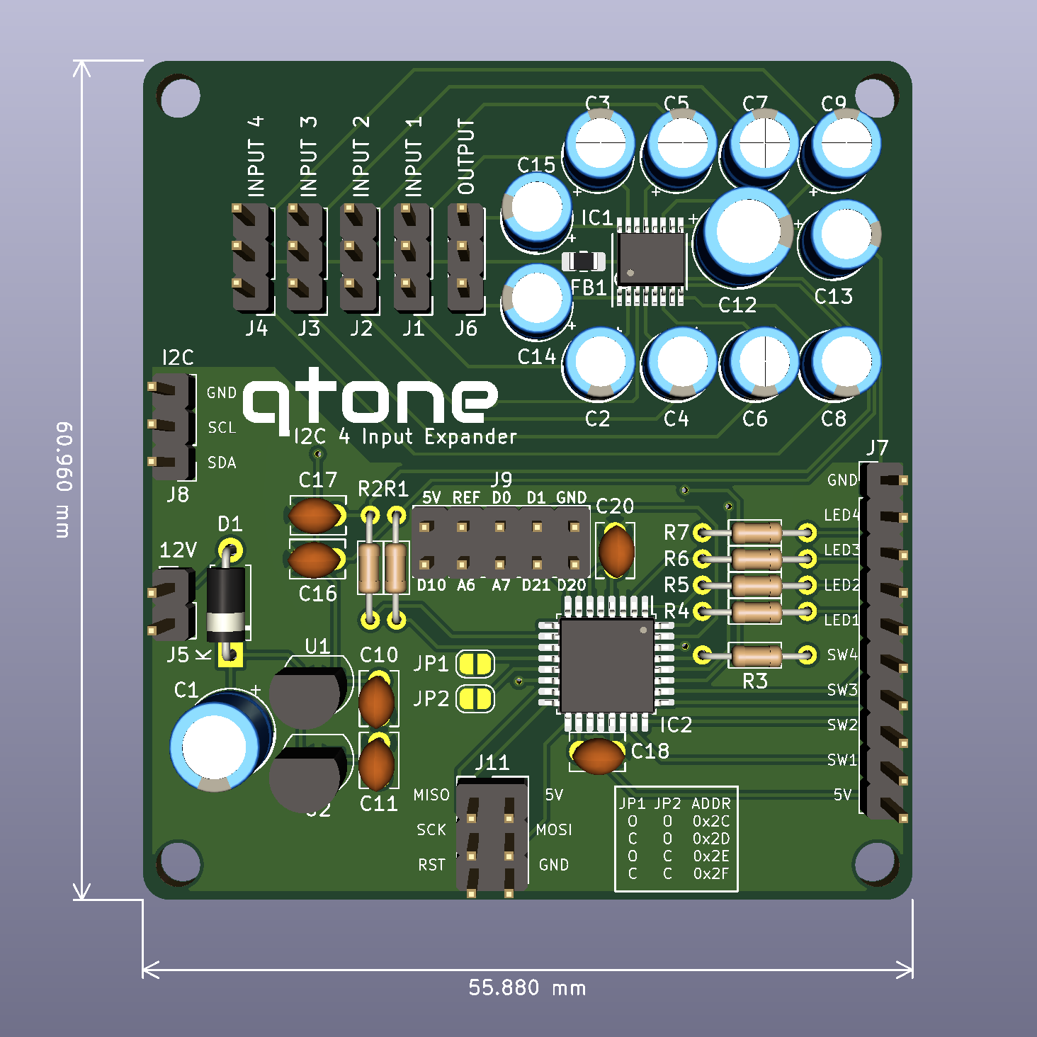
With the removal of the crystal an amount of board real-estate was freed and I have used that space to implement the "J9" connector. This connector simply connects to the unused pins, D0, D1, D10, D20, D21, [A]REF, A6 and A7 and breaks them out for any other uses. D0 and D1 are the UART pins, although given the internal OSC probably not that reliable in that mode. There seems to be no ham in bringing them out and someone might find a use for them as well.
As a side note for anyone who doesn't know, the A6 and A7 pins are analogue input exclusive so can not be used as digital IO.
Discussions
Become a Hackaday.io Member
Create an account to leave a comment. Already have an account? Log In.