 Sander van de Bor
Grocery shopping was easy where I grew up. The store was small, and the options limited. Need milk, you grab a carton, tea did not have thousands of different flavors and beer was just a Pilsener. Today is different and you can spend hours in the store since there are too many options, just like the peripherals on these new micro-controllers.
The ATMEGA328P used in the Arduino UNO is pretty good controller and suit most of my projects. It has some nice peripherals to other devices as you can see in the picture below:
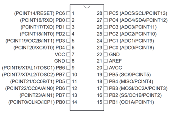
You can create an SPI connection with pins PB2 to PB5 (SS, MOSI, MISO and SCK). Have a “serial” (UART) connection with PD0 (RXD) and PD1 (TXD) and create a wire connection with PC4 (SDA) and PC5 (SCL). All the analog inputs are on PC0 (ADCx) up to PC5, but there is also a conflict since PC4 and PC5 were used for wire already. So, when you use wire, you basically only have ADC0 up ADC3 left for analog inputs since the others (ADC4 and ADC5) are used.
The more advanced 32 bits micro-controllers like the SAMD21G18A, used on the Arduino M0, has even more peripherals per pin. A pin could have up to 8 different peripherals and a conflict between pins is more common. Fortunately, unlike the ATMEGA328P, you can move certain peripherals around between certain pins when pins are used for something else. For example, with the issue above where we want to use all the analog input pins, there will be an option on more advanced micro-controllers to move the SDA and SCL pins to a different pins of even a PORT. This is all described in the PORT Function Multiplexing table and called PORTMUX. The ATMEGA4809 supports PORTMUX and so does the ATtiny1616. I will skip the more advanced micro-controllers and go straight to the ATtiny1616 since that has the easiest PORTMUX table I have worked with so far.
The PORTMUX table can be found on page#16 (chapter 5) of the ATtiny1616 datasheet:
http://ww1.microchip.com/downloads/en/DeviceDoc/ATtiny3216_ATtiny1616-data-sheet-40001997B.pdf
For our ATtiny1616 break-out board we want at least all the 3 serial communication options (USART, SPI and TWI) and as many PWM (TCA) and analog input pins (ADC). The ATtiny1616 even supports 1 analog output (DAC)! The PORTMUX table mentioned above is added to the pins_arduino.h variant file for reference as wel (see: https://github.com/SpenceKonde/megaTinyCore/blob/master/megaavr/variants/csat1616/pins_arduino.h).
You will notice that the columns USART0, SPI0, TWI0, TCA0, TCBn and CCL have the same description on multiple pins. For example, MOSI is shown behind PA1 and PC1. That does not mean the ATtiny1616 support two individual SPI peripherals, you must pick one of the two. You might also notice that one is in typewriter font which means that it is the alternative pin location for that peripheral.
Based on this table I was able to update the ASCII board lay-out from my previous log:
                          _____
                  VDD   1|*    |20  GND
 (nSS)  (AIN4) PA4  0~  2|     |19  16~ PA3 (AIN3)(EXTCLK)
        (AIN5) PA5  1~  3|     |18  15  PA2 (AIN2)(MISO)
 (DAC)  (AIN6) PA6  2   4|     |17  14  PA1 (AIN1)(MOSI)
        (AIN7) PA7  3   5|     |16      PA0 (nRESET/UPDI)
        (AIN8) PB5  4   6|     |15  13  PC3
        (AIN9) PB4  5   7|     |14  12  PC2
 (RXD) (TOSC1) PB3  6   8|     |13  11  PC1
 (TXD) (TOSC2) PB2  7~  9|     |12  10  PC0
 (SDA) (AIN10) PB1  8~ 10|_____|11   9~ PB0 (AIN11)(SCL)
For now I just picked all the standard locations, but I might move the SPI pins to PC0 to PC3 or use the ADC1 in the future since those pin in PORTC are available and not really used for something else besides regular I/O. Using alternative pin locations requires register changes which I will describe in another log. The following changes are made to the pins_arduino.h with the following settings for all Serial communication:
#define SPI_MUX              (PORTMUX_SPI0_DEFAULT_gc)
#define PIN_SPI_MISO    (15)
#define PIN_SPI_SCK        (16)
#define PIN_SPI_MOSI    (14)
#define PIN_SPI_SS        (0)

#define MUX_SPI            (SPI_MUX)
#define SPI_INTERFACES_COUNT    1

static const uint8_t SS   = PIN_SPI_SS;
static const uint8_t MOSI = PIN_SPI_MOSI;
static const uint8_t MISO = PIN_SPI_MISO;
static const uint8_t SCK  = PIN_SPI_SCK;

#define PIN_WIRE_SDA        (8)
#define PIN_WIRE_SCL        (9)

#define TWI_MUX         (PORTMUX_TWI0_DEFAULT_gc)

static const uint8_t SDA = PIN_WIRE_SDA;
static const uint8_t SCL = PIN_WIRE_SCL;

// Mapped to HWSERIAL0 in Serial library
#define HWSERIAL0                 (&USART0)
#define HWSERIAL0_DRE_VECTOR     (USART0_DRE_vect)
#define HWSERIAL0_DRE_VECTOR_NUM (USART0_DRE_vect_num)
#define HWSERIAL0_RXC_VECTOR     (USART0_RXC_vect)
#define HWSERIAL0_MUX             (PORTMUX_USART0_DEFAULT_gc)
#define PIN_WIRE_HWSERIAL0_RX     (6)
#define PIN_WIRE_HWSERIAL0_TX     (7)
The USART communication can be tested with a Serial to USB converter, for example the https://www.adafruit.com/product/3309, but any converter will work. Just connect the RxD pin on the converter to PB2 (TxD) in the ATtiny1616 and make sure they both share the ground. You could power the ATtiny1616 from the 5V connection of the converter as well when you don't have a power supply for your board yet. Here is a simple program written in Arduino to test the connection:
void setup() {
    Serial.begin(115200);
}

void loop() {
  for (int i = 0; i <= 10; i++) {
    Serial.print(i);
    Serial.print(" ... ");
    delay(500);
  }
  Serial.println("Hello World!");
}
Which will result in the following output:
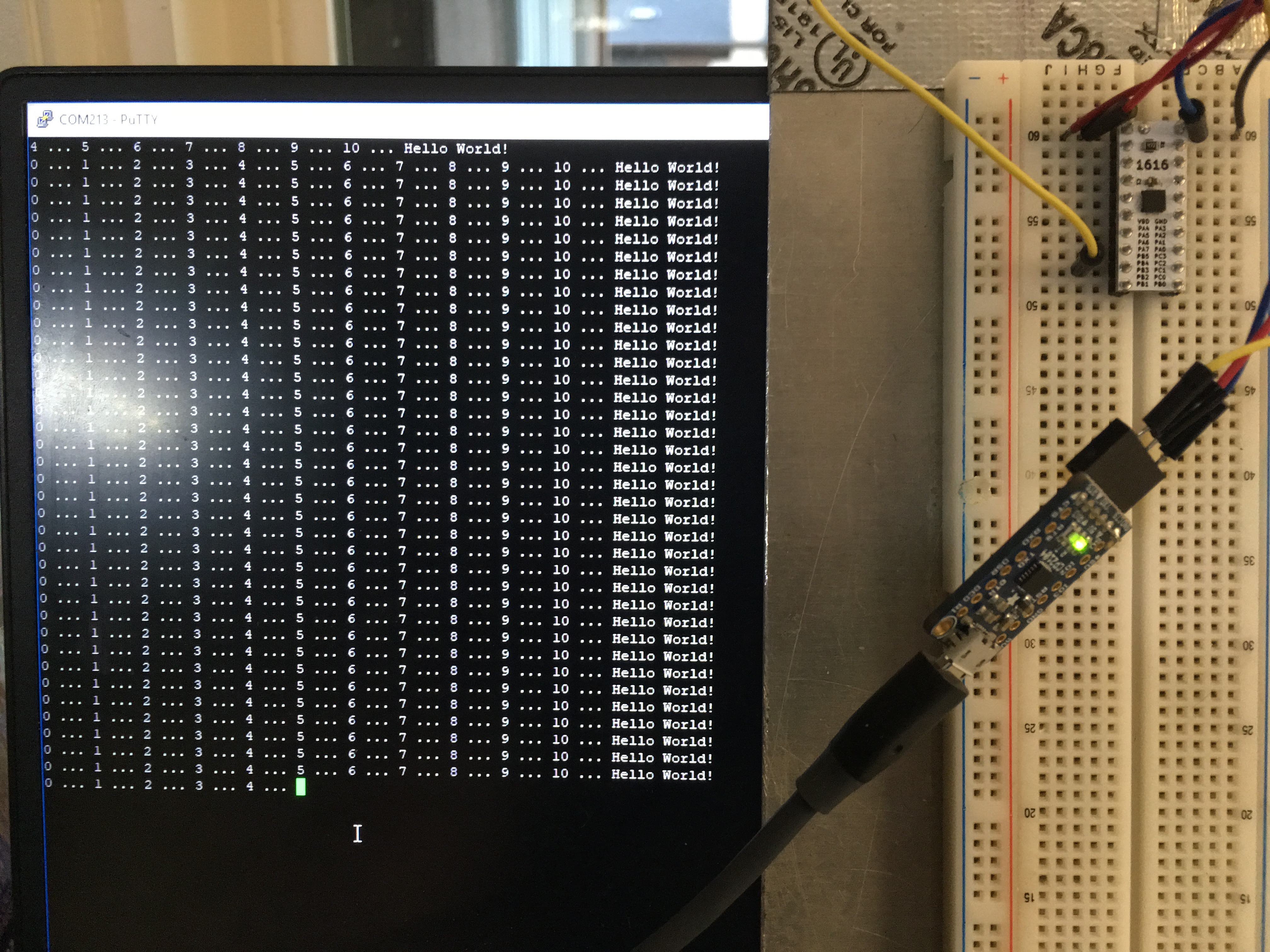
I used the program PuTTY to connect to the serial port since I have the programmer connected in Arduino and I did not want to switch between serial ports to establish a Serial Monitor connection.
Next I will explain the registers a little bit more in details. There is not a lot of documentation on these new chips and I have not found a clear explanation of how these should be programmed (structure wise) but I get a better understanding after reading the datasheet and playing with ATMEL start.
Discussions
Become a Hackaday.io Member
Create an account to leave a comment. Already have an account? Log In.
Thanks for this explanation! I could not understand ATtiny portmux until reading your article.
Are you sure? yes | no
👍 Bookmarked
Are you sure? yes | no