In the first log the structure of the Arduino was explained, together with the required components like the Device Family Pack (DFP) and the AVR-GCC compiler. We have been using the DFP in the last examples by using the macros defined in the IO files for each microcontroller to set registers. While most macros are very well described and could be used for almost everything there is an even more convenient solution for some peripherals; the AVR-GCC tool chain libraries!
In the first log was explained how certain commands in Arduino, like delay, are just functions called from the Arduino core (a collection of libraries). While the Arduino core has the major functions for the most used controls to pins and communication peripherals it just cannot do them all.
In the previous log for example the Real Time Counter (RTC) was used by setting registers since the RTC has not been developed for the Arduino core. At the end of that log I also mentioned that the CPU is still running while it is doing nothing. We have to put the CPU in sleep mode if we want to conserve energy. Like the RTC, sleep is not part of the Arduino core, so we must write to the registers ourselves.
Page#96 of the ATtiny1616 manual describes the different sleep modes: http://ww1.microchip.com/downloads/en/DeviceDoc/ATtiny3216_ATtiny1616-data-sheet-40001997B.pdf
11.3.1 Initialization describes the steps to setup the sleep mode. First we need an interrupt to get out of sleep mode which we already had set with the RTC of the previous log (ISR(RTC_CNT_vect)). Next, we must select the sleep mode (will get back to that later) and enable sleep mode with the enable bit. Enabling the sleep mode will not put the CPU to sleep, it just enabled sleep mode so that is can put the device to sleep when needed.
  SLPCTRL.CTRLA |= SLPCTRL_SMODE_PDOWN_gc;
  SLPCTRL.CTRLA |= SLPCTRL_SEN_bm;
After setting these bits in the register we must to send an instruction to put the MCU to sleep. While setting up the sleep mode and enabling is probably done only once and for that reason can be done in the setup, putting the CPU to sleep must be done after each time it wakes up, and in this example we can just add it to the main loop. Writing an instruction is new in this series of logs, but can be done as follows:
__asm__ __volatile__ ( "sleep" "\n\t" :: );
The code should be update as follows:
void setup() {
    pinMode(LED_BUILTIN, OUTPUT);
    RTC_init(1000);
    SLPCTRL.CTRLA |= SLPCTRL_SMODE_PDOWN_gc;
    SLPCTRL.CTRLA |= SLPCTRL_SEN_bm;
}

void loop()
{
    // time too sleep!
    __asm__ __volatile__ ( "sleep" "\n\t" :: );
}
While this works great, there is actually a cleaner method available within the AVR-GCC compiler libraries. We can find these libraries in the following location:
C:\Users\svandebor\AppData\Local\Arduino15\packages\arduino\tools\avr-gcc\7.3.0-atmel3.6.1-arduino5\avr\include\avr
There is a file called sleep.h which we will use on the sketch. On the top of the sketch add a line:
#include <avr/sleep.h>
#include <avr/sleep.h>
Now we can use the functions within this library instead of writing directly to the registers and creating instructions. The new code will look as follows:
#include <avr/sleep.h>

void RTC_init(int RTCdelay)
{
  RTC.CLKSEL = RTC_CLKSEL_INT32K_gc;    // 32.768kHz Internal Crystal Oscillator (INT32K)

  while (RTC.STATUS > 0);               // Wait for all register to be synchronized
  RTC.PER = RTCdelay;                   // Set period for delay
  RTC.INTCTRL |= RTC_OVF_bm;            // Enable overflow Interrupt which will trigger ISR
  RTC.CTRLA = RTC_PRESCALER_DIV32_gc    // 32768 / 32 = 1024 (sec) ~ 1 ms
  | RTC_RTCEN_bm                        // Enable: enabled
  | RTC_RUNSTDBY_bm;                    // Run In Standby: enabled
}

ISR(RTC_CNT_vect)
{
  RTC.INTFLAGS = RTC_OVF_bm;            // Clear flag by writing '1'
  digitalWrite(LED_BUILTIN, CHANGE);
}

void setup()
{
  pinMode(LED_BUILTIN, OUTPUT);
  RTC_init(1000);   // Start the RTC time counter, counting up to 1000 (~1 sec.)

  set_sleep_mode(SLEEP_MODE_STANDBY);  // Set sleep mode to STANDBY mode
  sleep_enable();
}

void loop()
{
  // nothing to do here
  sleep_cpu();
}
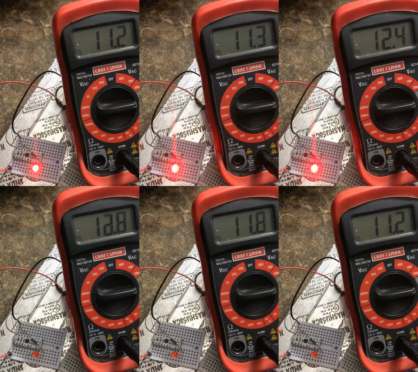
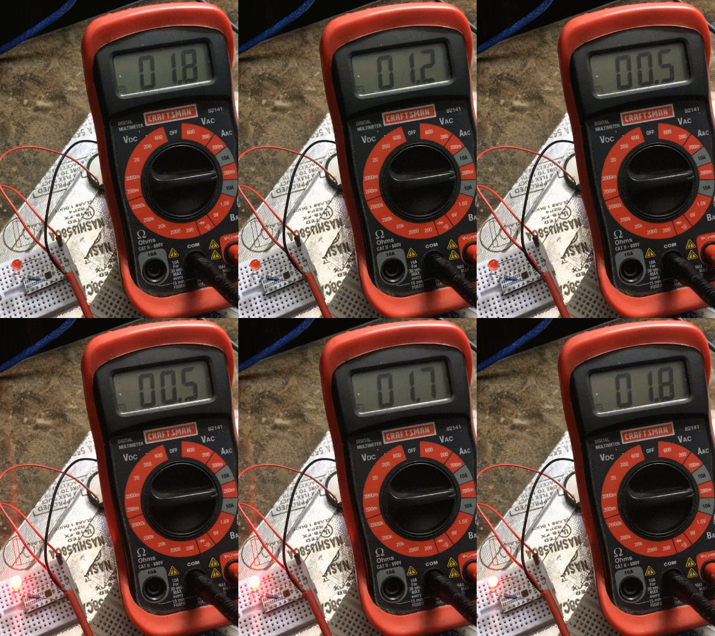
You can use a voltmeter to measure the current before and after these changes.

You will notice that the current when the LED is off will go from 11.2mA to about 0.5mA.

A great improvement, but we should be able to go below 20μA. Writing a similar code on Atmel Studio did indeed drop it down below at least 0.1mA (my cheapo voltmeter is not measuring low enough).

It looks like the current Arduino Core has some peripherals running which we should turn off before entering the sleep mode. That is currently beyond the scope of this log, but I will update later when I find a solution.
 Sander van de Bor
Discussions
Become a Hackaday.io Member
Create an account to leave a comment. Already have an account? Log In.