Discrete Electronics Guy
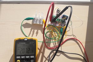
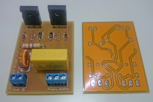
First we start with the oscillator part. It produce the necessary high frequency AC for the working of ignition coil. It is made by using the famous 555 timer IC. The 555 oscillator circuit produce the high frequency (in KHz range) square wave signal. But it is not capable of powering the ignition coil because its output current is too low. So wee add an extra buffer circuit for driving the ignition coil, which needs more current. For the buffer action we add an extra high power transistor to the output of the 555 oscillator circuit. The transistor boost the current and given to the ignition coil. Here the transistor and the ignition coil works at 24V DC and the oscillator circuit works at 9V DC from a battery. It is because the transformer (ignition coil) output voltage is increases when input voltage increases. The oscillator circuit is not work at this 24V, so it is power at a lower voltage. Her two independent power supply is used because when the ignition coil works, it produce high voltage surges (because it is an inductor) so it will damage the 555 IC. So for simplicity we use independent power supply to solve this problem. Other wise add some filters between the transformer (ignition coil) and circuit power supply lines and decrease the voltage to a lower level. The whole circuit diagram is given above. The 555 wired as an a stable multi vibrator. The potentiometer is used to change the oscillator frequency. It is used to fix the maximum output power point. The two circuit ground connected together to ensure the common ground otherwise the transistor will not work. OK.
The more detailed circuit explanation is given in my blog. Please visit it.
https://0creativeengineering0.blogspot.com/2019/01/high-voltage-power-supply.html
 Azri Jamil
 Sagar 001