Sponsor Link:
UTSource.net Reviews
It is a trustworthy website for ordering electronic components with cheap price and excellent quality.
Powering up this module
To power up this module for all of its function to completely work, you will need to make sure you have a stable +12 volt power supply and the CR1220 battery (as provided with this module). Then, make sure you follow the steps, as well as the images below: 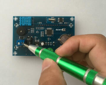 1. Flip the module onto its back side (screen facing down) and make sure the terminal screws are not tightened by rotating the screws anti-clockwise, as seen by the image above. You will need a flat head screwdriver to unscrew the terminal screws.
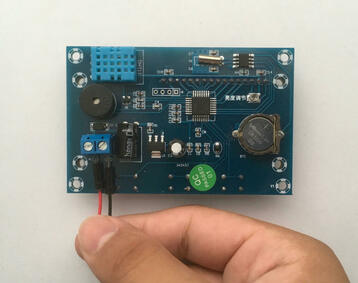 2. Insert your +12v (+) wire into the left terminal as marked by the labels on the PCB (printed circuit board). Then, for the right side of the terminal block, insert your GND (-) connection. Make sure the power going through the wires isn't active yet as it can be a shorting hazard when inserting it in.
 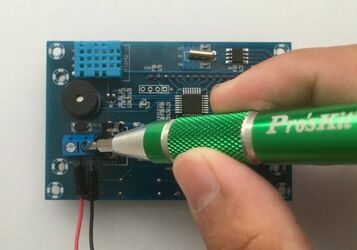 3. Once the wires are inside the terminal blocks, use a flat head screwdriver to tighten the screws on top of each terminal block by rotating the screws clockwise, and once that is done, make sure the wires are not able to be released easily.
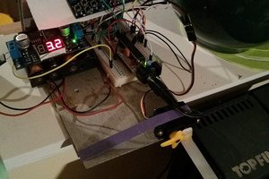
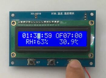
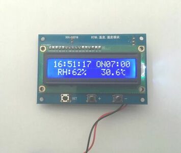 4. Now, you can flip the module onto its front side, turn the power through the wires on, and you will be able to see the LCD light up with all of the data on it (a picture of what is on the screen is above), thus indicating that the module has successfully powered up!
Changing the LCD contrast
Mainly depending on your environment's lighting conditions and whether this module is in an outdoor or indoor area, you may need to adjust the display contrast to your own preference. This alteration may greatly improve your view of the information displayed, and the screen from different perspectives. This can be done easily with the following steps below: 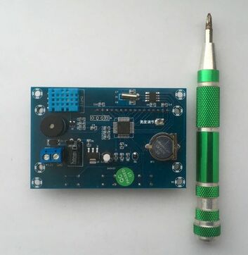 1. Flip the module onto its back side (with the display facing down) and make sure you have a Phillips head screwdriver with you, as seen in the image above.
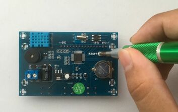 2. You will find a small screw implanted onto the back of this PCB (right above the battery) which you can adjust with your Phillips head screwdriver, depending on whether you want to increase the contrast or decrease the contrast. Rotate the screw clockwise or anti-clockwise in slight intervals to play around with this function and to really find the perfect contrast. I recommend turning the screw slightly every time, then glancing back at the display to see the change with every turn you make, until you have an ideal contrast level.
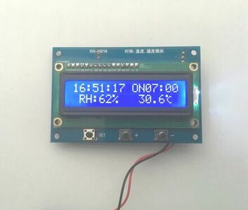 3. Once you have done that, flip the module back onto its front side (display side up) and you will see the display adjusted to your contrast changes.
Configuring the time
To configure the time on this clock module, it is fairly simple, where a few simple button clicks can do the job to allocate the correct time. Plus, after you have set the time you want, the button battery which you have placed in the back of this module beforehand, can remember the desired time for many months, or even years. If you try to turn the clock module off and on again, the time will still be remembered due to the CR1220 battery still powering the RTC (real time clock) chip, the DS1302. However, to set the right time first, please follow these steps below:  1. After you have powered the module on, press the "SET" button and you will see the the hour numerical figure blink, with an underline on the figure.
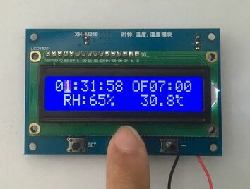
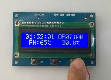 2. From there, you can use the "+" and "-" buttons to cycle through the 24-hour numerical values from 00 to 24 hours, depending on the timezone you are in to set the correct time.
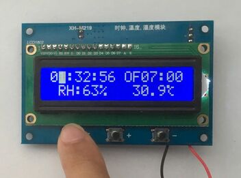 3. After you have set the correct hour, you would want to set the minutes and you can do this by pressing the "SET" button again directly after you have set the hours and the underline plus the flashing figure will move over to the minute figure.
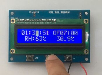
 4. Then, use the use the "+" or "-" button to cycle through the numerical...

 achan1989