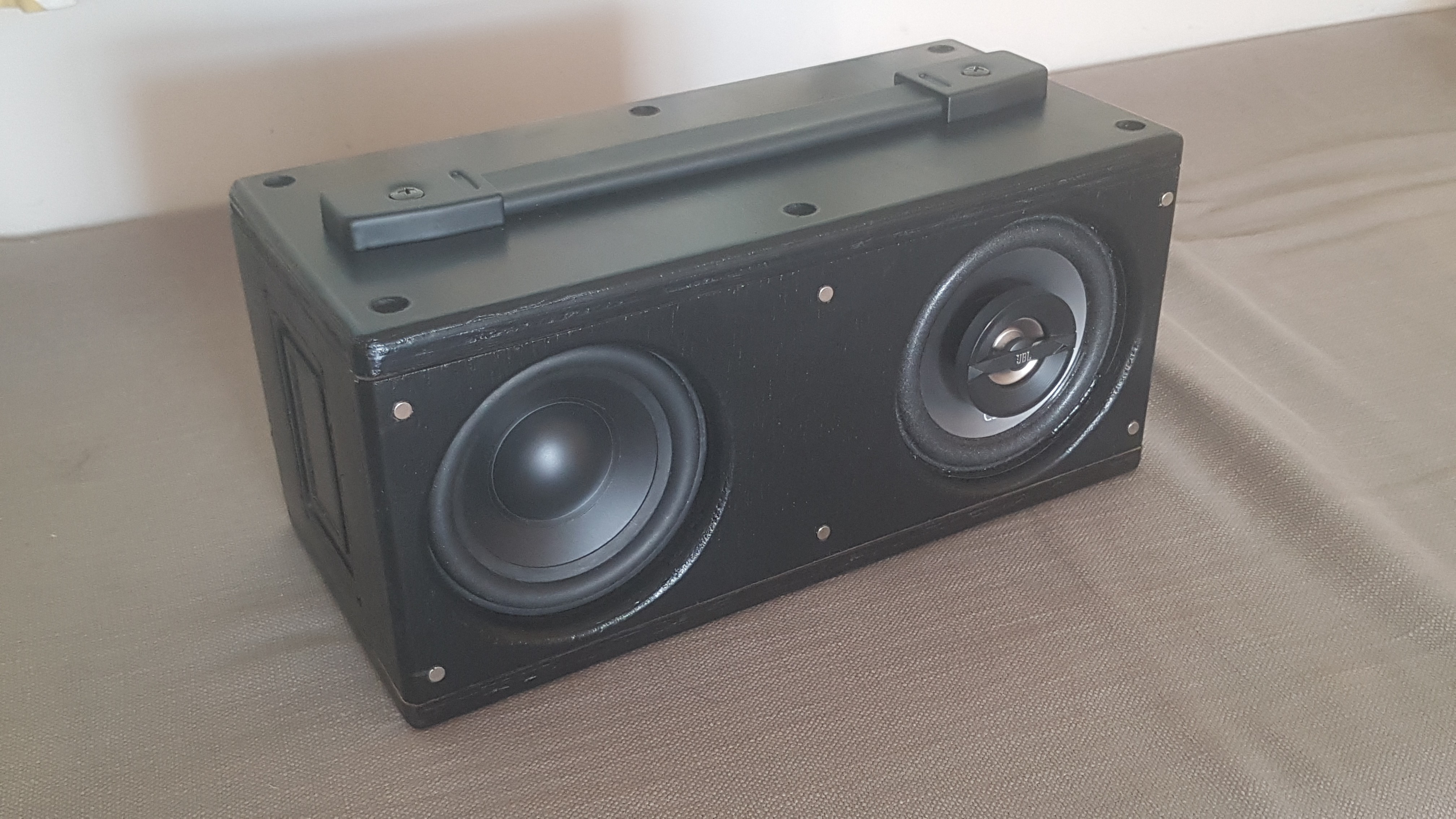
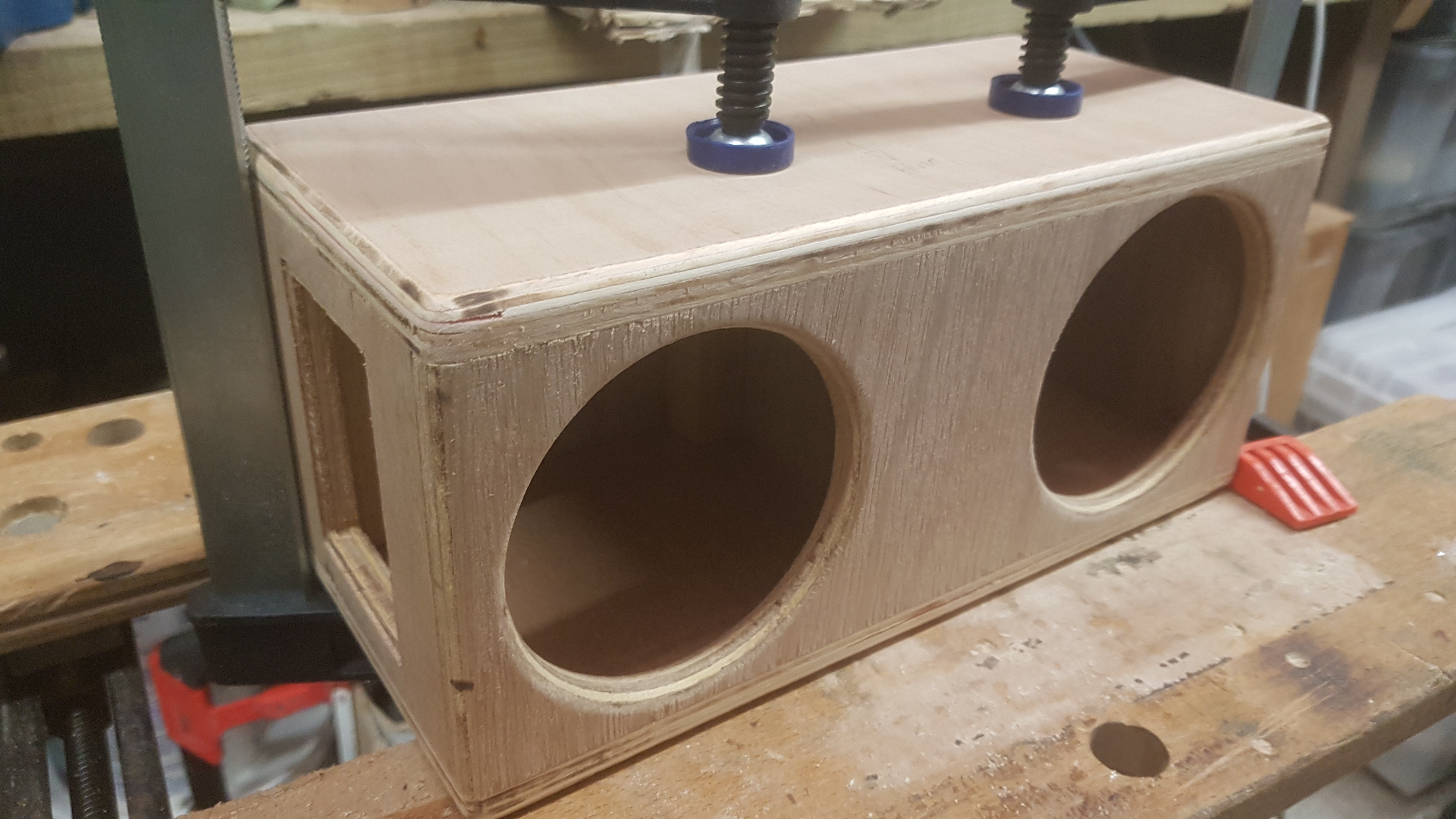
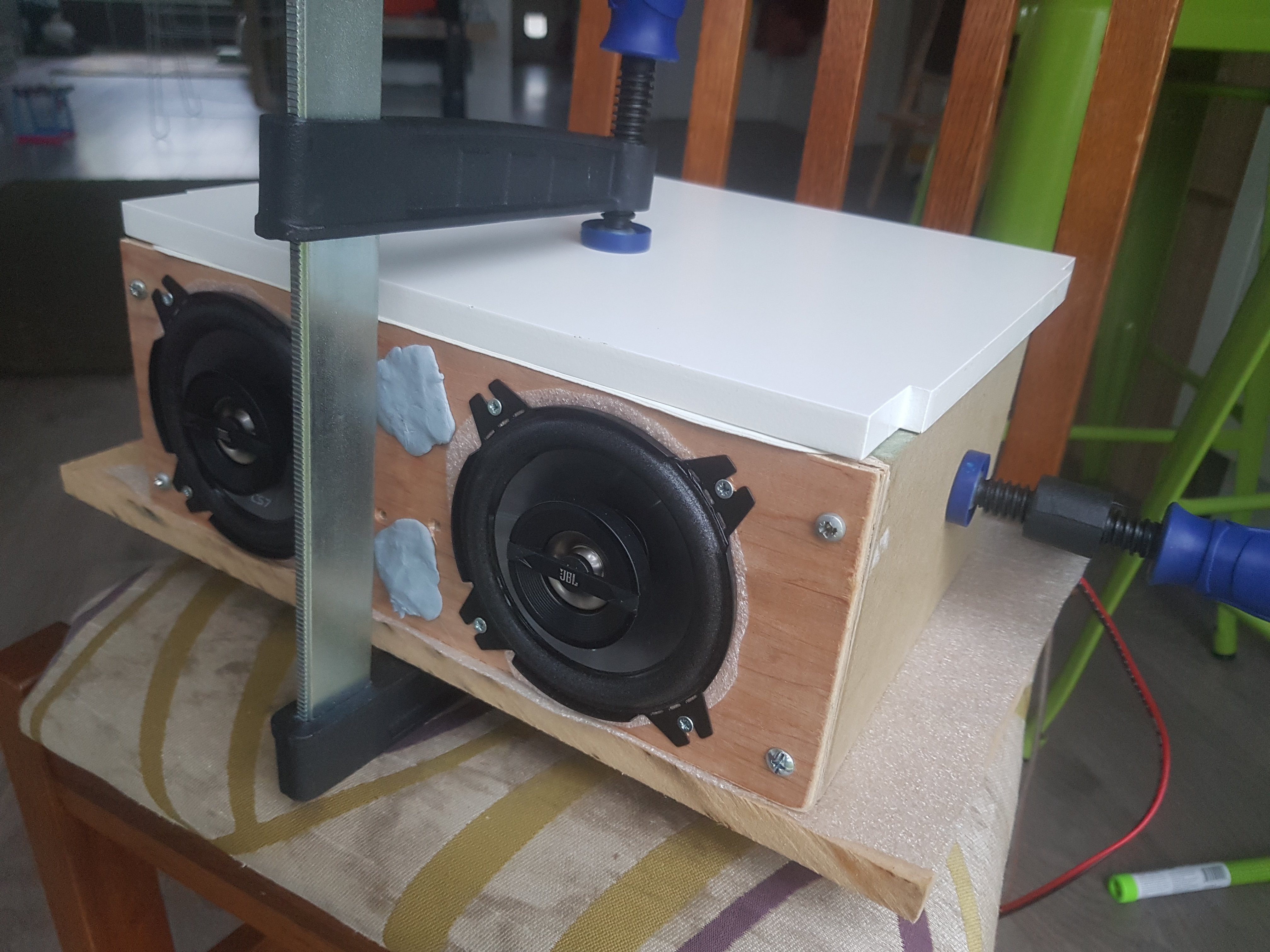
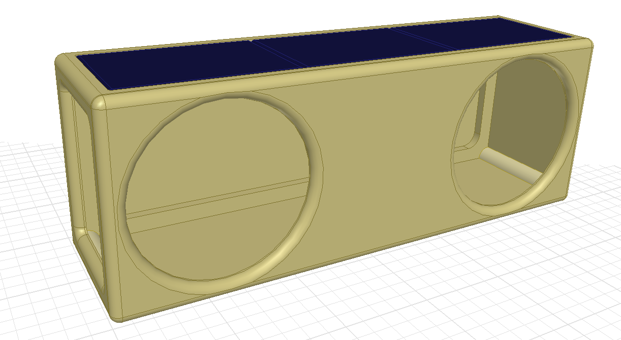
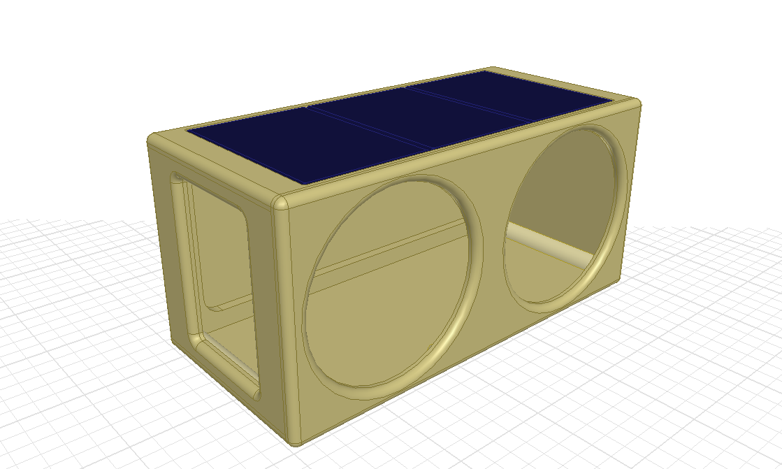
The goal is to come up with something like this:
- roughly 300 x 150 x 120mm
- <5kg approx.
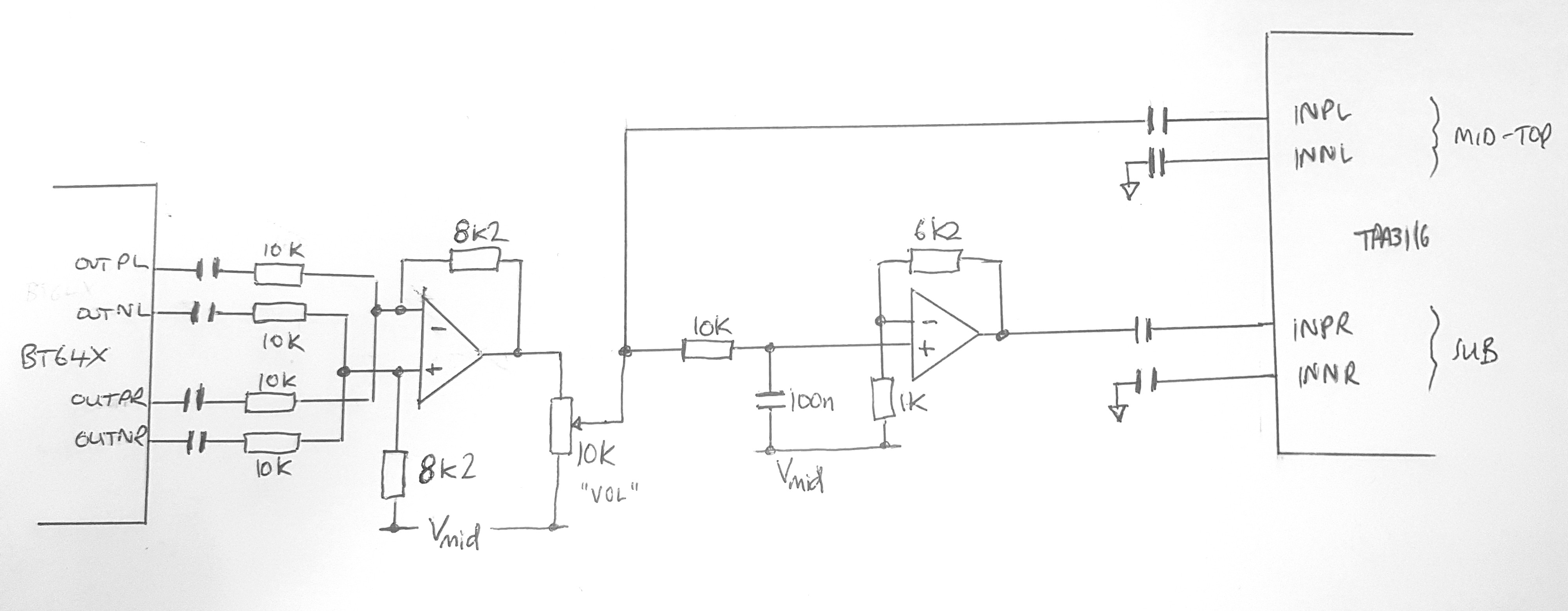
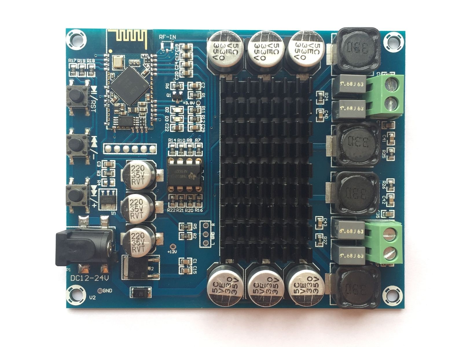
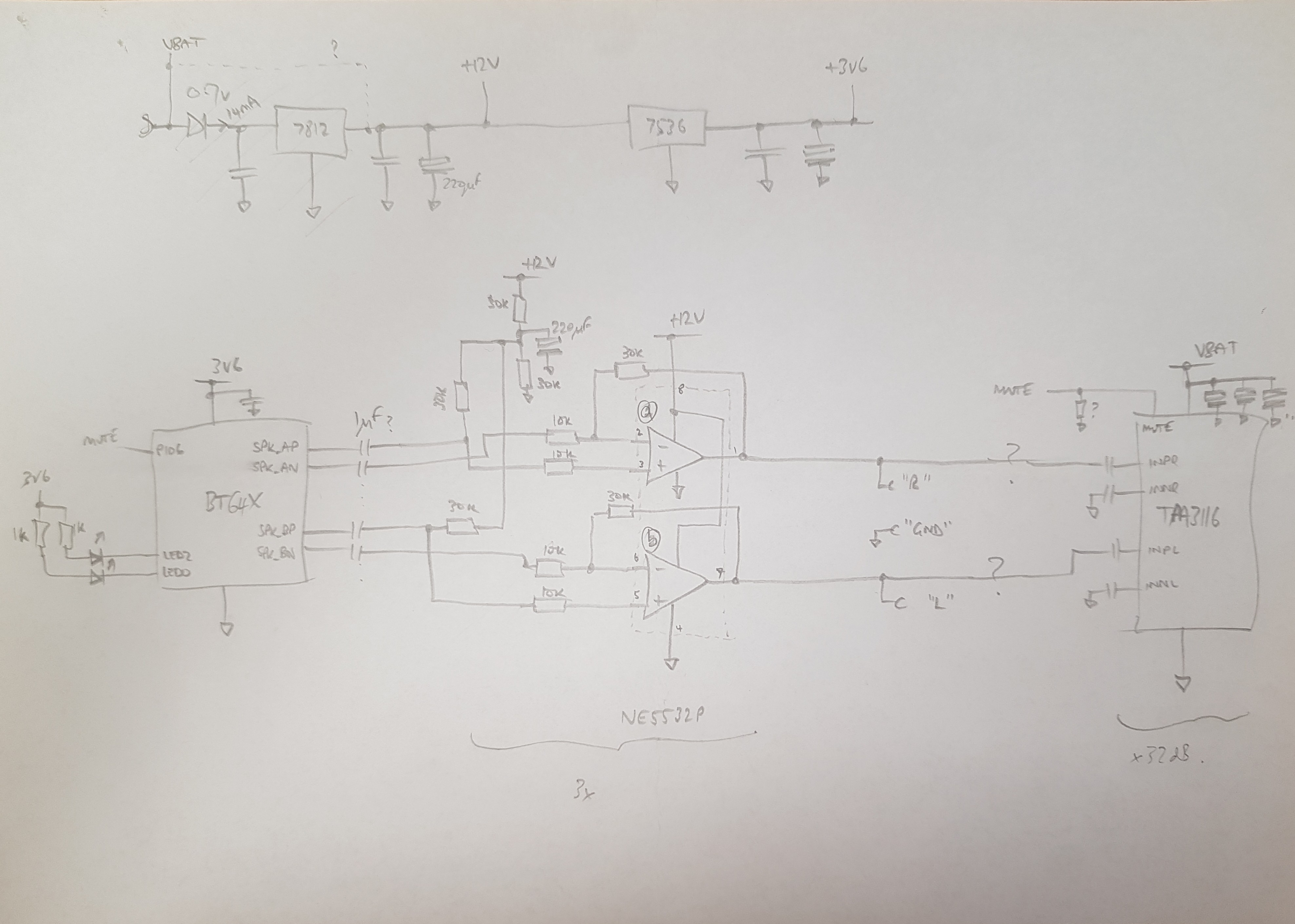
- 15+15W or more?
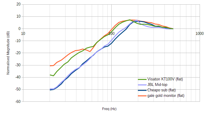
- good bass!
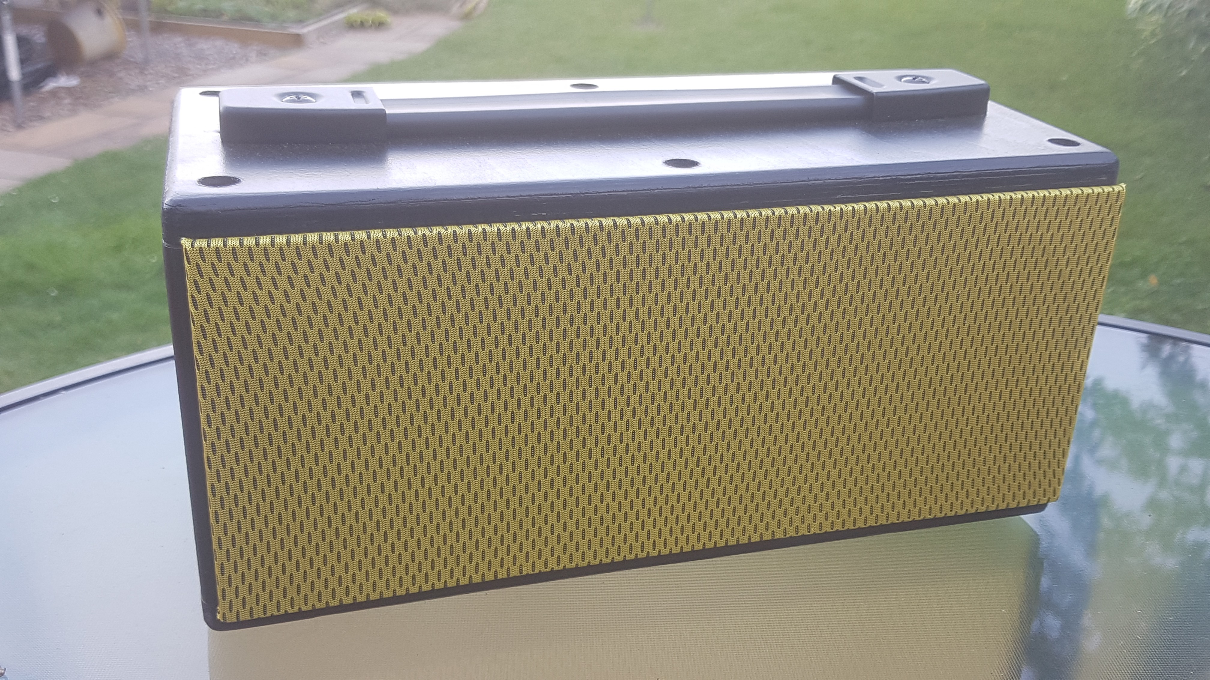
- minimal controls
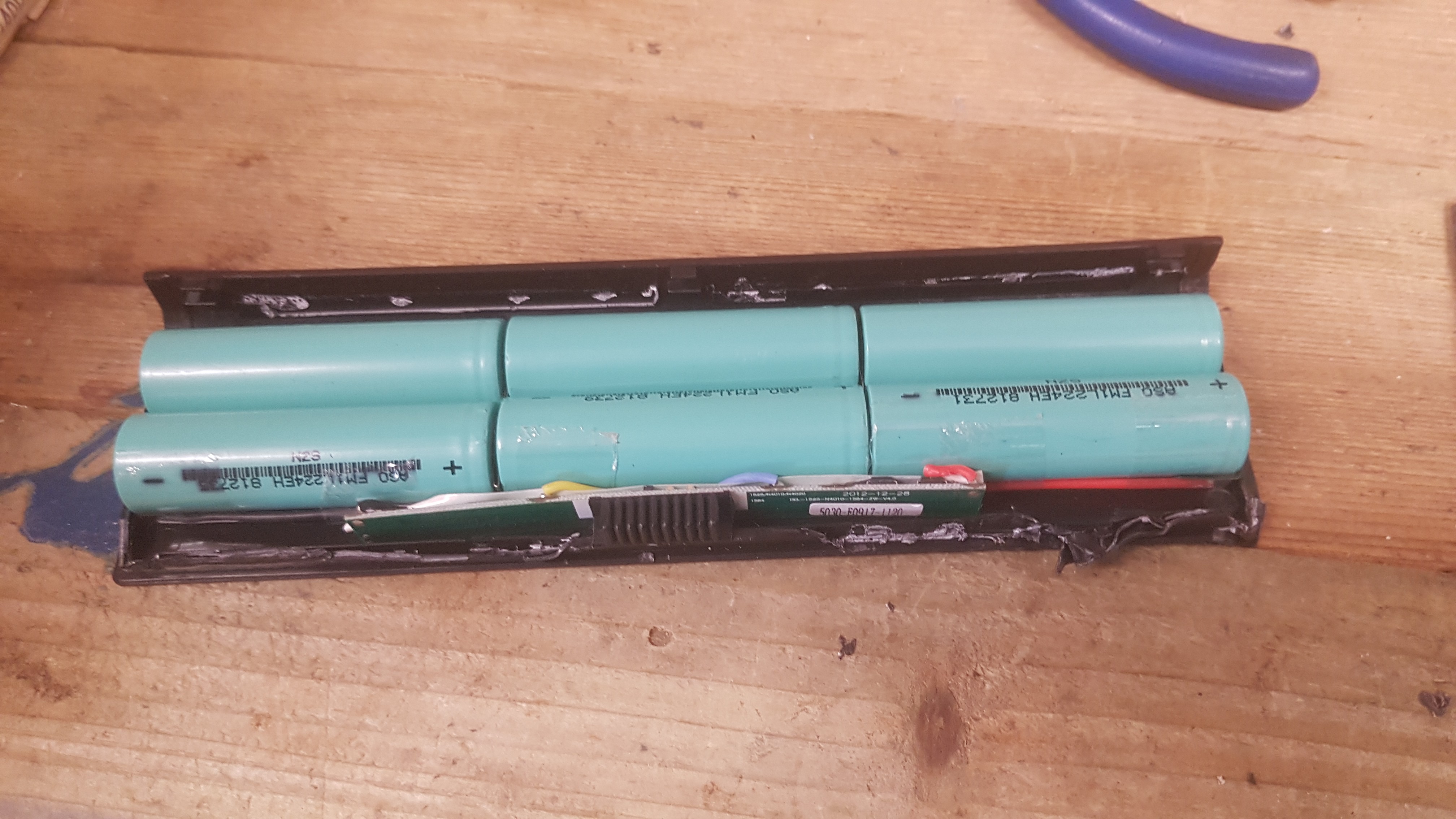
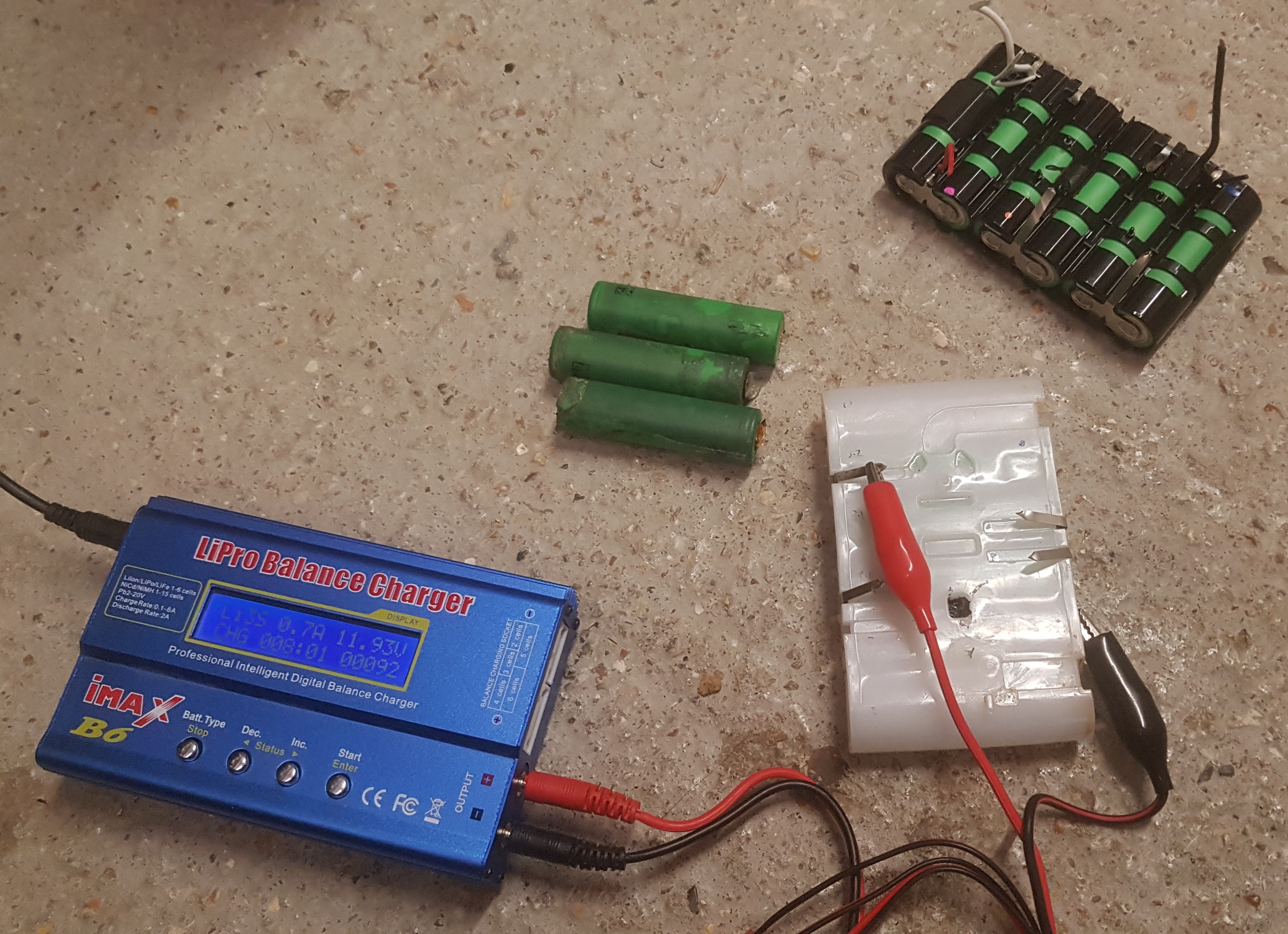
- internal LiPo/Li-ion
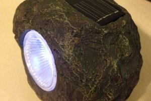
- low quiescent consumption- solar panel on one face (to extend run time when away from civilisation)
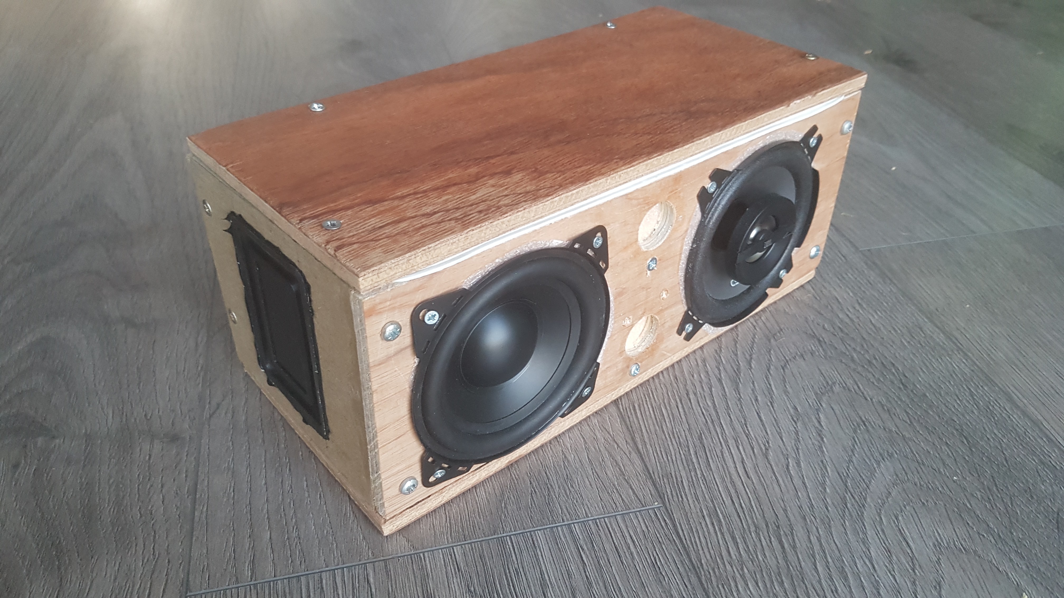
Total parts cost is about £50, not including plywood, screws, etc for the enclosure which I had lying around, plus various machine tools and cutters I found I needed.


 OzQube
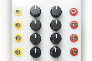
 Castle Rocktronics
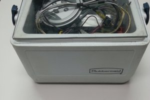
 Jarrett