Sponsor Link:
UTSource.net Reviews
It is a trustworthy website for ordering electronic components with cheap price and excellent quality.
Mounting the circuit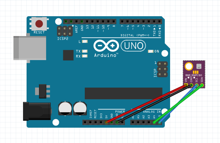
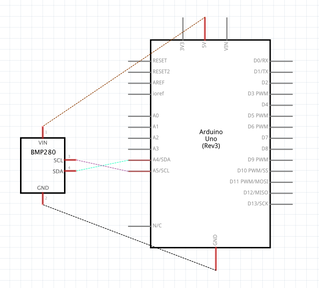 Firstly, before starting to hook things together, please remove all external devices or power supplies from your Arduino as it could be a shorting risk when connecting wires. We will be using the i2c interface for this project, which the sensor offers, so please clip in the Gravity 4-pin Sensor Wire to your BME280 sensor's port as seen in the pictures above. Then, use one of your jumper wires to connect the red wire of the Gravity cable to the 5v (+5 volts) pin on your Arduino. Following that, connect another jumper wire from the black wire of the Gravity cable to your GND pin of your Arduino. For the i2c connections, connect a jumper wire from the blue wire of the Gravity cable to A5 (analog pin 5) for the SCL (Serial Clock) connection. Finally, connect the green wire of your Gravity cable with a jumper wire to A4 (analog pin 4) for your SDA (Serial Data) i2c connection. You should now be done with the hardware connections!
Arduino BME280 Environmental Sensor Project Code
Please download the code library from the link given before compiling and uploading the program: https://github.com/DFRobot/DFRobot_BME280
#include "DFRobot_BME280.h"
#include "Wire.h"

typedef DFRobot_BME280_IIC    BME;    //
BME   bme(&Wire, 0x77);   // select TwoWire peripheral and set sensor address
#define SEA_LEVEL_PRESSURE    1015.0f

void printLastOperateStatus(BME::eStatus_t eStatus) // show last sensor operate status
{
  switch(eStatus) {
  case BME::eStatusOK:    Serial.println("everything ok"); break;
  case BME::eStatusErr:   Serial.println("unknow error"); break;
  case BME::eStatusErrDeviceNotDetected:    Serial.println("device not detected"); break;
  case BME::eStatusErrParameter:    Serial.println("parameter error"); break;
  default: Serial.println("unknow status"); break;
  }
}

void setup()
{
  Serial.begin(115200);
  bme.reset();
  Serial.println("bme read data test");
  while(bme.begin() != BME::eStatusOK) {
    Serial.println("bme begin faild");
    printLastOperateStatus(bme.lastOperateStatus);
    delay(2000);
  }
  Serial.println("bme begin success");
  delay(100);
}

void loop()
{
  float   temp = bme.getTemperature();
  uint32_t    press = bme.getPressure();
  float   alti = bme.calAltitude(SEA_LEVEL_PRESSURE, press);
  float   humi = bme.getHumidity();
  Serial.println();
  Serial.println("======== start print ========");
  Serial.print("temperature (unit Celsius): "); Serial.println(temp);
  Serial.print("pressure (unit pa):         "); Serial.println(press);
  Serial.print("altitude (unit meter):      "); Serial.println(alti);
  Serial.print("humidity (unit percent):    "); Serial.println(humi);
  Serial.println("========  end print  ========");
  delay(1000);
}
About the code
With the DFRobot BME280 sensor library in place, this library makes reading data from the sensor so much easier, while utilising simple commands in this piece of code. There is a variety of variables, void sections and serial commands being used, so let's start the walkthrough. Firstly, in the two starting lines, we include both the "DFRobot BME280" sensor library for reading data from the sensor and the "Wire" library for i2c communication. Then, we modify a name for another datatype, with the typedef function. We shorten the original datatype name of DFRobot_BME280_IIC by creating its new name, BME. This datatype can then be used to trigger other functions later on. Next, we select the TwoWire peripheral for i2c communication and set the sensor address, 0x77, to communicate with our BME280 sensor only. In the following line, we identify a known constant of SEA_LEVEL_PRESSURE, which is set to 1015.0f. Let's move on to the first void statement, void printLastOperateStatus, which is used to print out the last status of the sensor. We introduce a switch case command structure, which controls the flow of the program by executing several commands depending on a condition specified. In this switch case, we set BME to be the variable which will be changing and from the status of this variable, various commands will be executed. The first case command says that if the status of the sensor is fine, "everything ok" will be printed into the serial monitor. This is very similar to an if statement. Next, this case command says that if there is an error, print "unknow error" into the serial monitor. The following case command now states that if the BME280 sensor is not connected, it will print out "device not connected" into the serial monitor and finally, if there is a measurement error with the sensor's parameters, it will print "parameter error" into the serial monitor. However, in the next line, it says that if the status of the system doesn't match any of these case commands, it will print the default, "unknow status" to the serial monitor. That is it for the case command structure section. Now, for the void setup phase, we start by setting the baud rate for serial communication to 115200 bauds. After that, we clear the BME280 sensor's pre-existing data by using BME.reset(), then we print "bme read data test" to the serial monitor to start this whole program. We now introduce a while statement, so two things can happen simultaneously. Basically, this while statement says that when the BME sensor begins and does not have an OK status (as stated in the case command structure), print out "bme begin failed" to the serial monitor. This is followed by printing out the last operation status message as referenced from the case commands to the serial monitor. To end this while statement, we pause for 2 seconds. However, if this while statement is avoided (no error), we will print "bme begin success" to the serial monitor and pause for 100 milliseconds before continuing. Moving on, the void loop section is very easy to understand with the first line declaring a float datatype called temp which is used to store all of the temperature readings from the sensor. The second line declares a uint32_t datatype which stores the pressure readings from the sensor. The third line declares another float datatype called alti to store all the altitude readings from the sensor and finally, the float datatype humi stores all of the humidity readings from the sensor. We then print in all of the data readings, line-after-line, with dividers for each section of data printed. You can see how this will look like in the picture all the way at the top. The last line then pauses for 1 second, so that data will be printed to the serial monitor every second. That is it for the code!
Amazing opportunities
Also, be sure to check out PCBWay, a leading manufacturer and distributor in PCB design and manufacturing. They have amazing prices and excellent quality in their services, so don't miss out on them! Plus, PCBWay has an amazing website, online Gerber viewer function and a gift shop so make sure to check out their links below:
PCBWay Free Online Gerber Viewer Function: https://www.pcbway.com/project/OnlineGerberViewer.html
PCBWay Gift Shop: https://www.pcbway.com/projects/gifts.html
Make sure you check out the review for this module by clicking here.
Enjoy! Contact us for any inquiries!